


5
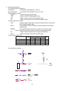
2.3 Power supply specifications
1) Power voltage : DC24V 5%
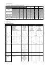
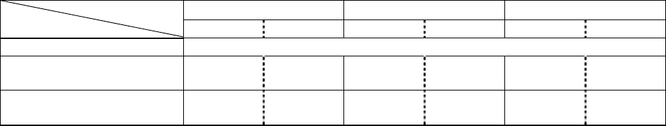
2) Current consumption *2, *3
NP-215/225 NP-325 NP415W
1 partition 2 partition 1 partition 2 partition 1 partition 2 partition
Standby Approx. 0.1A
ASCII printing
(Printing average of 16%)
Approx.
1.4A
Approx.
0.9A
Approx.
1.7A
Approx.
1.1A
-
Approx.
1.3A
Bit image printing
(Max 100%)
Approx.
6.0A
Approx.
3.2A
Approx.
7.8A
Approx.
4.1A
-
Approx.
5.7A
*2: A sufficient volume of power supply is required to maintain print quality due to high peak current
that may run according to printing.
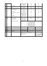
*3: If power supply cable is excessively long, the operation may become unstable. Cable should be
made as short as possible. If not available, connect cables near the printer and place an electrolysis
condenser of 2200 between power supply and ground. Voltage resistance should be higher than
35V.
* For preventing from static electric discharge, make sure to connect FG wire.
2.4 Reliability
1) Head life : Average resistance change rate to head less than 15%, except
defects caused by dust or others
Pulse : More than 100 million pulses (with recommended paper)
Wear distance : More than 50 km (with recommended paper)
2) Operation environment : Temperature 0 – 45
Print guarantee 5 - 40 , no condensation
3) Storage environment : Temperature -20 - 60
* When storing for a long time, paper must be kept loaded between head and platen.
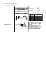
4) Frame Ground (FG) wire
The FG wire (Green and Yellow) is coming from the printer body. Make sure to ground the wire
near the body frame when installing the printer. FG grounding is effective for minimizing the noise
level, preventing from SED and maintaining the FG safety for head, cutter, body frame, power
supply and Data connectors.
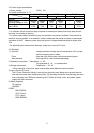
5) Safety regulation
CE marking
UL60950
6) EMC
EMI: EN55022
VCCI: Class A
FCC: Class A
EMS: EN55024