


TABLE OF CONTENTS
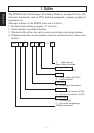
1. Outline ...............................................................................................................1
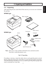
2. Unpacking and Installation ................................................................................2
2-1. Unpacking ..............................................................................................2
2-2. Locating the Printer................................................................................3
2-3. Handling Care ........................................................................................3
2-4. Maintenance ...........................................................................................3
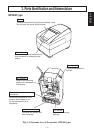
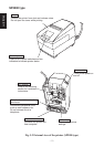
3. Parts Identification and Nomenclature ..............................................................4
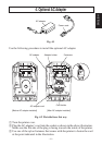
4. Optional AC Adapter.........................................................................................6
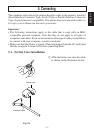
5. Connecting.........................................................................................................8
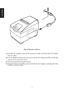
5-1. Ferrite Core Installation .........................................................................8
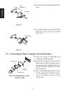
5-2. Connecting to Host Computer (Serial Interface) ...................................9
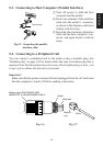
5-3. Connecting to Host Computer (Parallel Interface) ..............................10
5-4. Connecting to a Peripheral Unit...........................................................10
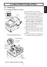
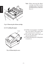
6. Loading the Ribbon Cartridge and Paper ........................................................12
6-1. SP2300 Type ........................................................................................12
6-2. SP2500 Type ........................................................................................15
6-3. Removing the Paper .............................................................................23
7. Control Panel ...................................................................................................24
7-1. Basic Operation....................................................................................24
7-2. Errors ...................................................................................................25
7-3. Switch Operation (Combined Switch Operation) ................................26
8. Optional Near-end Sensor ...............................................................................30
8-1. Adjusting the Near-end Sensor ............................................................30
Appendix A: General Specifications .................................................................128
Power Supply Specifications......................................................................131
Appendix B: Serial Interface .............................................................................132
B-1. Pins and Signal Names ......................................................................132
B-2. Interface Connections (Serial Interface) ............................................133
Appendix C: Parallel Interface ..........................................................................134
C-1. Table of Connection Signals for Each Mode .....................................134
Appendix D: DIP Switch Setting ......................................................................136
D-1. Parallel Interface ................................................................................136
D-2. Serial Interface ...................................................................................138
Appendix E: Memory Switch Settings ..............................................................141
Appendix F: Peripheral Unit Driver Circuit .....................................................142