


132
APPENDIX
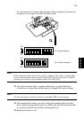
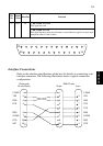
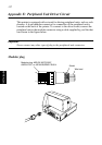
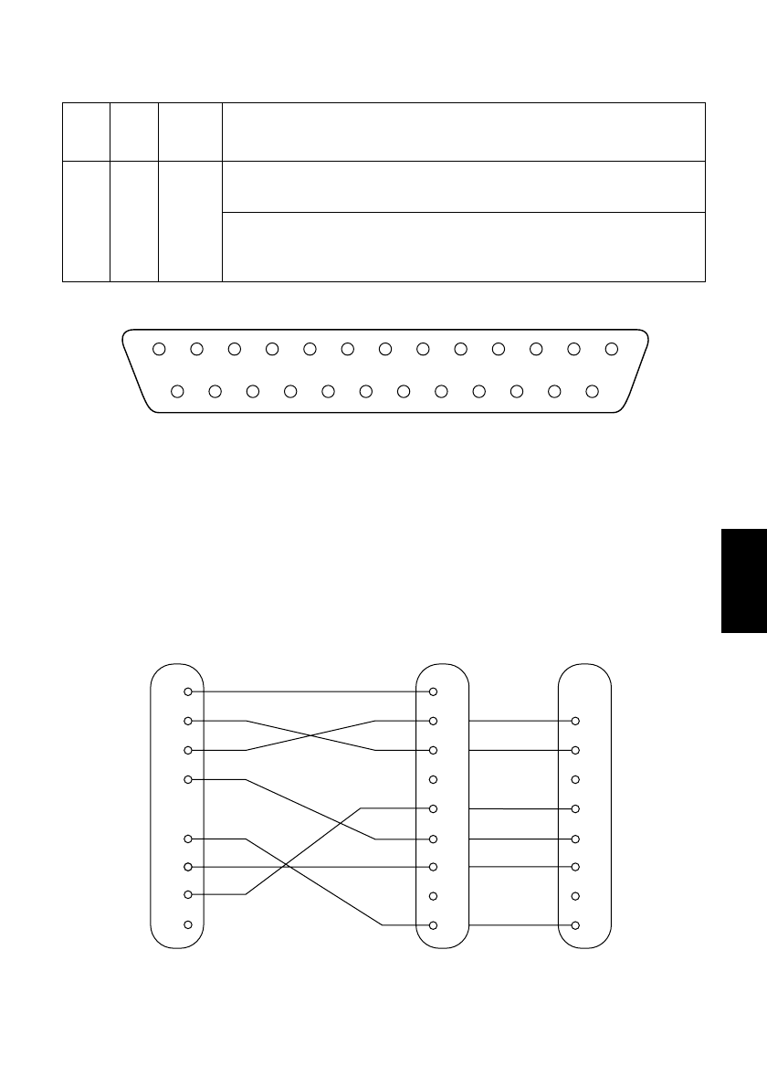
Interface Connections
Refer to the interface specifications of the host for details on connecting to its
interface connector. The following illustration shows a typical connection
configuration.
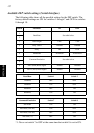
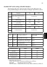
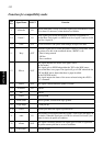
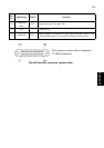
25 INIT IN • DIP Switch 10 = OFF
This signal not used.
• DIP Switch 10 = ON
This signal becomes reset signal. Printer is reset whenever signal is in space state
with pulse width of 1mS or more.
Pin
No.
Signal
Name
Direction Function
13
25
1
14
1
2
3
4
6
1
2
3
4
5
6
7
8
20
F-GND
TXD
RXD
RTS
DSR
20
25
7
S-GND
DTR
INIT
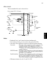
Printer side
(D-sub 25 pin)
IBM PC side
3
2
7
8
6
5
1
4
F-GND
TXD
RXD
RTS
CTS
DSR
S-GND
DCD
DTR
9 pin25 pin