


– 52 –
c) If the printer receives a <DC1> n code (n is the DIP
switch controlled address) during the addressable
mode (with DIP switches 4-1 to 4-4 set other than
settings a) and b) above,), the deselect mode is canceled
and data following this code is input to the buffer.
Note that addressable mode is valid only when op-
tional RS-422A interface is installed.
(2) When using parallel interface printer;
When the printer receives a <DC1> code, the deselect
mode is canceled and data following this code is input to
the buffer.
FUNCTION
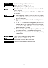
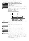
Select uni-directional print mode
CODE
<ESC> “U” “1” or <ESC> “U” <1>
(1B)
H (55)H (31)H or (1B)H (55)H (01)H
OUTLINE
Prints only when the print head moves from left to right.
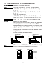
FUNCTION
Select bi-directional print mode
CODE
<ESC> “U” “0” or <ESC> “U” <0>
(1B)
H (55)H (30)H or (1B)H (55)H (00)H
OUTLINE
Returns to the standard bi-directional print mode. (This mode
is set automatically when the printer power is turned on.)
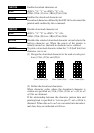
FUNCTION
Initialize printer
CODE
<ESC> “@”
(1B)
H (40)H
OUTLINE
Initializes all the commands already set. However the follow-
ing parameters are not initialized: eternal device drive pulse
width setting, operation switch valid/invalid selection, online
switch valid/invalid selection. Also, the line and data buffers
are not cleared and the DIP switches are not read in again.
For a serial interface printer, the select/deselect state for
addressable mode and DC1/DC3 mode is not affected.