


TABLE OF CONTENTS
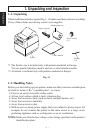
1. UNPACKING AND INSPECTION......................................................1
1-1. Unpacking ....................................................................................1
1-2. Handling Notes ............................................................................1
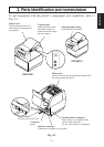
2. PARTS IDENTIFICATION AND NOMENCLATURE ......................2
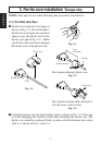
3. FERRITE CORE INSTALLATION *EUROPE ONLY ...................... 3
3-1. Parallel interface ..........................................................................3
3-2. Peripheral unit cable.....................................................................4
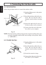
4. CONNECTING THE INTERFACE CABLE ....................................... 5
4-1. Serial interface ............................................................................. 5
4-2. Parallel interface ..........................................................................5
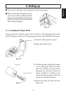
5. SETTING UP ........................................................................................6
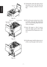
5-1. Loading the Paper Roll ................................................................6
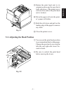
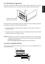
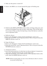
5-2. Adjusting the Head Position ........................................................8
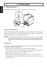
6. CONTROL PANEL ..............................................................................9
6-1. Basic Operation............................................................................9
6-2. Power switch and ON LINE/FEED switch combinations ......... 10
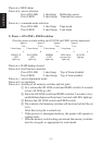
6-3. Print Density Adjustment........................................................... 12
6-4. Sensor Adjustment Mode........................................................... 12
6-5. Errors..........................................................................................14
6-6. Buzzer Sounding Variations ......................................................15
APPENDIX A: SPECIFICATIONS........................................................64
A-1. General Specifications ..............................................................64
A-2. Paper Specifications ..................................................................65
APPENDIX B: DIP SWITCH SETTING ...............................................68
B-1. Serial Interface ..........................................................................69
B-2. Parallel Interface........................................................................69
APPENDIX C: SERIAL INTERFACE...................................................70
C-1. Connectors and Signal Names (Serial Interface) ......................70
C-2. Interface Connections ................................................................ 71
APPENDIX D: PARALLEL INTERFACE ............................................72
D-1. Table of Connection Signals for Each Mode ............................72
APPENDIX E: PERIPHERAL UNIT DRIVE CIRCUIT....................... 74
APPENDIX F: MEMORY SWITCH SETTINGS ..................................76