


– 70 –
APPENDIX
Appendix C: Serial interface
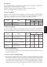
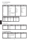
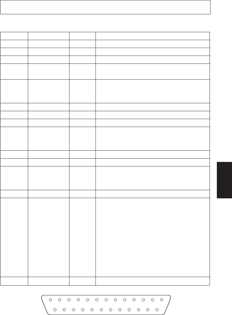
C-1. Connectors and Signal Names (Serial Interface)
Pin No. Signal name
Direction
Function
1 F-GND – Frame ground
2 TXD OUT Outgoing data
3 RXD IN Incoming data
4 RTS OUT Request To Send: The printer sets this signal
on “SPACE” when it is ready to send.
5 CTS IN The host sets this signal on “SPACE” when it
is ready to send. NOTE: The printer does not
monitor this signal.
6 N/C Not used
7 S-GND – Signal ground
8 ~ 10 N/C Not used
11 RCH OUT The printer sets this signal on “SPACE” when
it is ready to receive. This pin outputs the same
signal as pin 20, to which it is connected.
12 N/C Not used
13 S-GND – Signal ground.
14 FAULT OUT The printer sets this signal on “MARK” to
indicate an error condition (machine error, no
paper, etc.).
15 ~ 19 N/C Not used
20 DTR OUT Data Terminal Ready: The printer sets this
signal on “SPACE” when it is ready to receive.
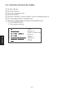
(1) DTR/DSR mode
Space when receiveis enable.
(2) X-On/X-Off mode
Always space except during following
states
• Period between reset and communica-
tion enable
• During self printing
21 ~ 25 N/C Not used
13 1
14
25