To test the cables already installed (RJ45, RJ11, USB and BNC):
1. Connect one end of the cable to the master’s proper connector.
2. Separate the remote module, then connect it to the cable’s remote point.
3. Press the test button.
4. When the LEDs stop flashing the result is ready to be read.
Note 1: Do not connect the tester to a live circuit.
Note 2: Do not test more than one cable simultaneously.
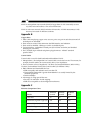
To test Ethernet 10Base2/10Base5 terminator value (BNC):
1. Disconnect any one of the T-connectors from its attached node on the 10Base2
segment that you want to test, and link the T-connector to the testers BNC port.
2. Press the test button.
3. When the LEDs stop flashing the result is ready to be read.
Note 1: Before conducting the test, verify there isn’t any activity on the 10Base2 segment.
Note 2: If testing LED fails to light after pressing the test button, replace the battery.
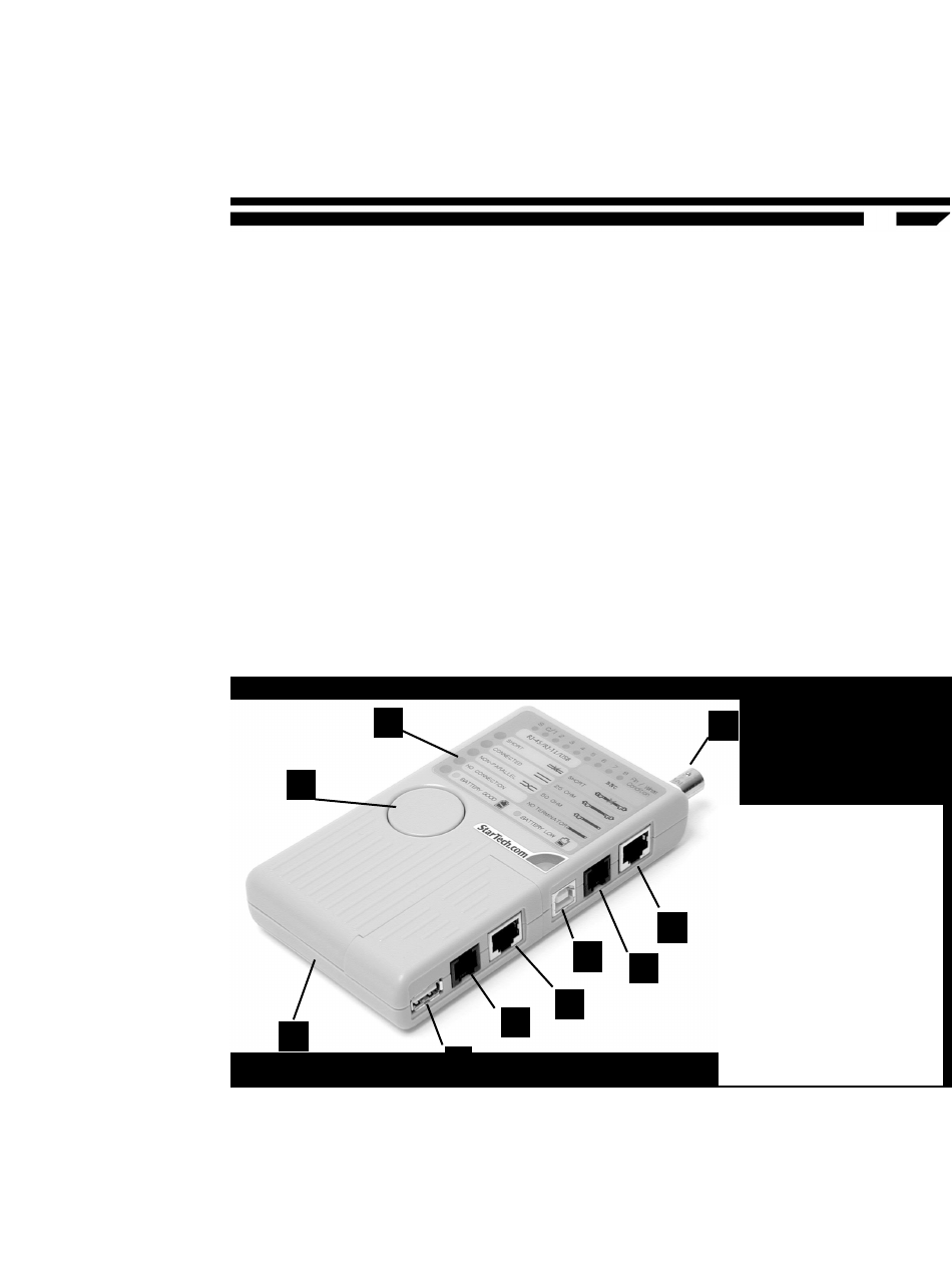
Key components
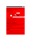
How to Read the Results
Testing RJ45, RJ11, USB and BNC
Short Test
When LEDs for Short, S, and 3 are on and the tester beeps four times, it means the Wire
number 3, 4 and 5 are short.
1. Operating push button
2. Battery cover (on back)
3. BNC connector
4. Shielded RJ45 connector
5. RJ11 connector
6. USB B connector
7. LED indicator
(Refer to Appendix A)
A. Shielded RJ45
connector
B. RJ11 connector
C. USB A connector
3
4
5
6
A
B
C
2
1
7
2


