


STUDER INNOTEC SI
User manual SI V3.0 E 5
Adjustments
(Not automatic with Twinpower version)
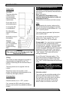
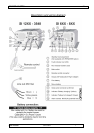
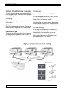
Standby Level (1)
The activation of the inverter, when working in
automatic mode, is dictated by the detection of a
load. With this function, it is possible to adjust
the minimum load detected between 0,3 and 20
Watts. This level is factory adjusted to 2
watts and so no further adjustment will
probably be needed.
Adjustment procedure
Make sure that no device is connected.
Check for the presence of hidden users such as
television, fax, video, … which often have a
standby mode and remain working even after
being turned off !
Put the switch in “ Autom. ” position.
Introduce a screw driver N°1 delicately in the
hole (1) provided and turn gently until you feel
the screw driver insert in the groove of the
screw.
Turn clockwise
until tight without pressing
(do not force!).
Wait until the green LED blinks.
Activate the minimum charge you wish to detect.
Turn the screw slowly anti-clockwise
without pressing until the inverter activates.
(green LED illuminated).
Check that the inverter goes back to standby
mode a couple of seconds after deactivation of
all charges.
Warning : In maximum anti-clockwise position
the inverter continues to work even if there is no
load
.
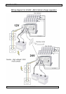
Control
The tension of the batteries is submitted to
control. During their use, the tension must be
between the following ranges :
11.4 V and 16 V in the 12 Volt models,
22.8 V and 32 V in the 24 Volt models,
45.6 V and 61 V in the 48 Volt models.
Outside these ranges the inverter is
automatically disconnected.
These values correspond to a no load situation
and they are automatically adjusted according to
the current of the battery.
The internal temperature and the maximum
power are also submitted to control.
In the case of prolonged overload or deficient
ventilation it is not possible to restart the inverter
until it has cooled down.
Indicators
Green Run - LED (3)
Illuminated: the inverter is connected. A 230 V
tension is present in the outlet.
Blinking : (only SI version) The inverter is in
“ Autom. ” mode and no voltage is detected by
the standby system.
A 230 V tension is intermittently present!
Red Fault - LED (2)
The inverter is stopped :
The tension of the battery is not correct
After an overload, overheating or short circuit
To restart the inverter after a failure, put the
switch (4) in “ OFF ” position for 10 seconds,
then connect again
.
Safety
The inverter is internally protected against
overloads and short circuits. Should this
protection fail, the inverter is equipped with a
fuse (fire protection). If the fuse is broken,
qualified technicians should control the
installation and change the fuse.
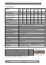
Internal fuse
Fuse Inverter SI (mod.)
40A 648
50A 624 - 1248
60A 824 – 1448
80A 612 – 2348 - 2360
100A 812 – 1224 – 3548 - 3060
2*100A 1212 – 1624 – 2324
2*125A 3324
The use of higher fuse value will not improve the
performance of the inverter and will degrade
safety protection !