Model 46 User Guide Issue 2, September 2007
Studio Technologies, Inc. Page 21
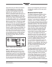
completion, the power LED will light
steadily. The settings for the four hybrid
circuits are stored in non-volatile memory
and will be recalled during the power-up
process.
Level Meters
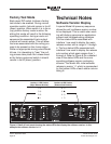
The Model 46 contains eight 5-segment
LED level meters. These meters are pro-
vided as a support aid during installation,
configuration, operation, and trouble-
shooting. The meters represent the sig-
nals coming in from, and going out to,
the 4-wire connections. The meters are
organized in four groups each represent-
ing one input and one output. They are
calibrated to reflect the level in dB rela-
tive to the configured nominal operating
level. This is similar to the way in which
now-legacy VU meters functioned. As an
example let’s take the situation where the
nominal operating level of an interface is
configured for +4 dBu and an output (“to
4-wire”) LED labeled “0 dB” is lit. (For this
example, the level on the 2-wire PL circuit
is just large enough to light the “0” LED.)
This indicates that a signal with an approx-
imate level of +4 dBu is present on the as-
sociated 4-wire output connector. Another
example would be a Model 46 interface
configured for +8 dBu operation and a
–12 dB LED is lit. This indicates that a
signal with audio level of –4 dBu is
present on its associated output.
Each level meter contains four green
LEDs and one yellow LED. The four green
LEDs indicate signal levels at or below the
configured nominal level. The top LED is
yellow in color and indicates a signal that
is 6 dB or greater than the nominal level.
An audio signal that causes the yellow
LED to light doesn’t necessarily indicate
an excessive level condition, but it does
provide a warning that at some stage
reducing the signal level may be prudent.
Normal operation with normal signal levels
should find the meters lighting near their
0 dB point. Signal peaks may cause the
yellow LEDs to flash. But a yellow LED that
lights fully during normal operation will
typically indicate a signal level or configu-
ration problem.
If the “from 4-wire” meters display consis-
tency lower or higher levels than their 0 dB
points it’s possible that a configuration is-
sue exists. One potential problem is incor-
rectly set 4-wire nominal audio level DIP
switches for one or both of the Model 46’s
interfaces. If the nominal level is set too
low then sufficient audio headroom might
not be available. It can also result in ex-
cessively-high audio signals being sent to
2-wire party-line circuits. Setting the nomi-
nal level for too high a value will reduce
the signal-to-noise performance. And, as
expected, it may also result in audio sig-
nals being sent to the 2-wire circuits at
too low a level. Begin a review by confirm-
ing that the two 4-wire level DIP switches
associated with each interface are set as
required.
If the Model 46’s 4-wire nominal levels
are set correctly but the meters still reflect
sub-optimal levels, the issue may be relat-
ed to incorrect settings on the equipment
connected to the 4-wire inputs and out-
puts. It’s possible that although a connect-
ed 4-wire device’s nominal level matches
the Model 46’s level setting, its actual
nominal level may be significantly differ-
ent. With a digital matrix intercom system
this problem could be due to an incorrect
configuration having been made to a spe-
cific channel or port. For example, the RTS


