


40 Sun StorEdge T3 and T3+ Array Configuration Guide • August 2001
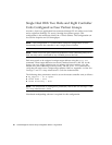
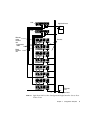
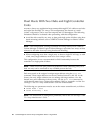
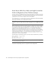
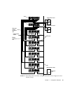
Dual Hosts With Two Hubs and Eight Controller
Units
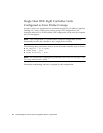
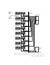
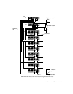
FIGURE 4-9 shows two application hosts connected through FC-AL cables to two hubs
and eight Sun StorEdge T3+ arrays. This configuration, also known as a multi-
initiator configuration, can be used for footprint and I/O throughput. The following
limitations should be evaluated when proceeding with this configuration
■ Avoid the risk caused by any array or data path single point of failure using host-
based mirroring software such as VERITAS Volume Manager or Solaris Volume
Manager.
Note – This configuration, running host-based mirroring features from VERITAS
Volume Manager or Solaris Logical Volume Manager, represents four arrays of data
mirrored to the other four trays using host-based mirroring.
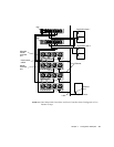
■ When configuring more than a single array to share a single FC-AL loop, as with
a hub, array target addresses need to be set to unique values.
This configuration is not a recommended for RAS functionality because the
controller is a single point of failure.
Note – There are no hub port position dependencies when connecting arrays to a
hub. An array can be connected to any available port on the hub.
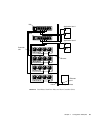
Each array needs to be assigned a unique target address using the port set
command. These target addresses can be any number between 1 and 125. At the
factory, the array target addresses are set starting with target address 1 for the
bottom array and continuing to the top array. Use the port list command to
verify that all arrays have a unique target address. Refer to Appendix A of the Sun
StorEdge T3 and T3+ Array Administrator’s Guide for further details.
The following two parameters must be set on the master controller unit, as follows:
■ cache mode = auto
■ cache mirroring = auto
Note – For information on setting these parameters, refer to the Sun StorEdge T3 and
T3+ Array Administrator’s Guide.