119
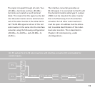
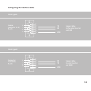
RS 485+
RS 485+
RS 485–
RS 485–
GND_G
TX
RX
GND_G
TX2
RX2
RS 485+
RS 485+
RS 485–
RS 485–
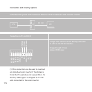
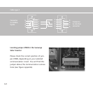
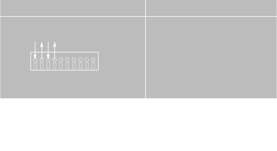
Connection to modem via RS 485/RS 232
In order to connect several solar inverters to
the remote monitoring, the interface converter
is connected directly to a modem via RS 232.
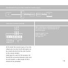
Jumper JP400 is connected to the solar inverter
that is furthest away from the interface conver-
ter. It must be open for all other solar inverters.
Stripped length: 11 mm
Jumper JP400: see above
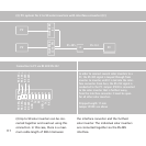
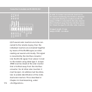
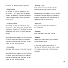
(4) If several solar inverters are to be con-
nected to the remote inquiry, then the
individual inverters are connected together
by means of the RS 485 signal, as when
reading out several units locally. This signal
is converted by the interface converter
into the RS 232 signal, from where it is led
to the modem using cable type C. Jumper
JP400 must be closed at the solar inverter
that is furthest away from the interface
converter. For all other solar inverters it
must be open. An address must be alloca-
ted, to enable identification of the indivi-
dual solar inverters. This is described in
Chapter 2.3 Commissioning, under
«Configuration».


