


Electrical connection and cable entry
For installation, please observe the
instructions in the "Setup" leaflet!
94
!
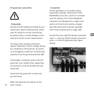
If the solar inverter is fixed to the installa-
tion frame, the electrical connection can
be led through. The unit may only be ope-
ned by a qualified electrician. The cabinet
cover must first be released and removed.
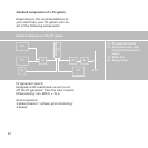
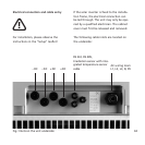
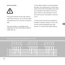
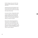
The following cable inlets are located on
the underside:
–DC +DC
RS 232, RS 485,
Irradiation sensor with inte-
grated temperature sensor
cable
AC wiring loom
L1, L2, L3, N, PE
–DC
+DC
Fig.: Inlets on the unit underside