


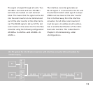

118
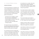
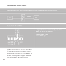
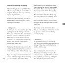
The signal is looped through all units. Two
«RS 485+» terminals and two «RS 485-»
terminals are located on each terminal
block. This means that the signal can be led
into the solar inverter at one terminal and
out of the solar inverter at the other termi-
nal. The RS 485 signal is led out of the last
solar inverter in the series into the interface
converter using the following configuration:
«RS 485+» to «DATA+» and «RS 485-» to
«DATA-».
The interface converter generates an
RS 232 signal. It is connected to the PC with
the standard modem cable type D. Jumper
JP400 must be closed at the solar inverter
that is furthest away from the interface
converter. For all other solar inverters it
must be open. An address must be alloca-
ted, to enable identification of the indivi-
dual solar inverters. This is described in
Chapter 2.3 Commissioning, under
«Configuration».
PC
IC
INVERTER
(2 to 99)
INVERTER
(1)
PV
PV
MODEM
MODEM
RS 232
RS 232
RS 485
(4) PV system for 2 to 99 solar inverters with interface converter (IC) and modem for
remote inquiry