


96
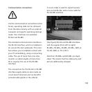
You must use adequately dimensioned
cable cross-sections in order to avoid a
considerable increase in the grid impedan-
ce between the domestic distribution and
the solar inverter. The terminal range of
the AC terminals is 0.5 to 6 mm2 for rigid
cables and 0.5 to 10 mm2 for flexible
cables. With a high grid impedance, i.e.
with a long line or too small a cross-
section, the voltage increases at the grid
terminal during feed-in.
If the terminal voltage exceeds the per-
missible value, the solar inverter is discon-
nected from the grid.
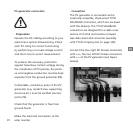
Carefully perform the following steps:
· Check that there is no voltage before
introducing the supply main into the
unit.
· Lead the 5-core AC cable (outer diame-
ter 9 – 17 mm) through the M25 threa-
ded cable gland.
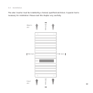
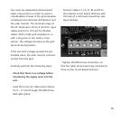
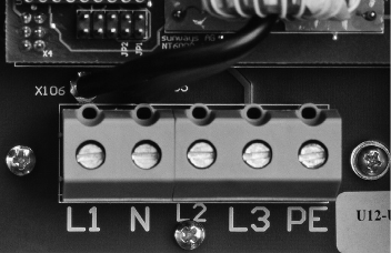
· Connect cables L1, L2, L3, PE and N to
the relevant circuit board terminal with
the help of a slot-head screwdriver (see
figure below).
· Tighten the M25 screw connection, so
that the cable cannot exert any mechanical
force on the circuit board terminal.