


2-22
X8DAH+/X8DAH+-F/X8DAH+(-F)-LR User's Manual
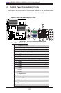
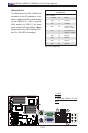
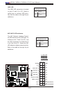
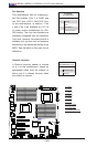
Power Button
OH/Fan Fail LED
1
NIC1 LED
Reset Button
2
HDD LED
Power LED
Reset
PWR
Vcc
Vcc
Vcc
Vcc
Ground
Ground
1920
Vcc
X
Ground
NMI
X
Vcc
PWR Fail LED
NIC2 LED
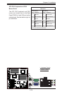
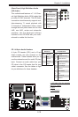
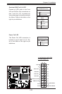
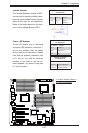
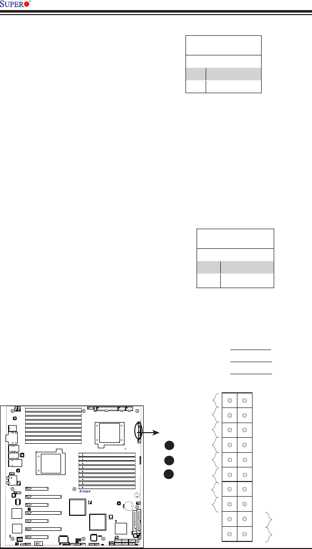
NIC1/NIC2 LED Indicators
The NIC (Network Interface Control-
ler) LED connection for GLAN port 1 is
located on pins 11 and 12 of JF1, and
the LED connection for GLAN Port 2
is on Pins 9 and 10. Attach the NIC
LED cables to display network activity.
Refer to the table on the right for pin
denitions.
GLAN1/2 LED
PinDenitions(JF1)
Pin# Denition
9/11 Vcc
10/12 Ground
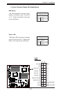
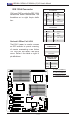
A
B
C
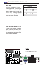
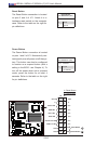
A. HDD LED
B. NIC1 LED
C. NIC2 LED
HDD LED
The HDD LED connection is located
on pins 13 and 14 of JF1. Attach a
cable here to indicate HDD activi-
ties. See the table on the right for pin
denitions.
HDD LED
PinDenitions(JF1)
Pin# Denition
13 +5V
14 HD Active
X8DAH+
Rev. 2.01