


5-4
A+ SERVER 2042G-TRF/6RF User's Manual
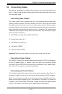
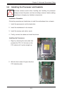
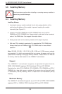
5-4 I/O Ports
The I/O ports are color coded in conformance with the PC 99 specifi cation. See
Figure 5-2 below for the colors and locations of the various I/O ports.
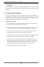
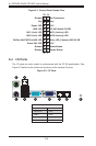
Figure 5-1. Control Panel Header Pins
Figure 5-2. I/O Ports
Power Button
2 1
20 19
Ground
Key
Power LED
HDD LED
NIC1 (Link) LED
NIC2 (Link) LED
OH/Fan Fail/PWR Fail/UID LED
Power Fail LED
Ground
Ground
No Connection
Key
3.3V
FP UID Switch/3.3VSB
NIC1 (Activity) LED
NIC2 (Activity) LED
Blue_LED_Cathode (UID)/5V SB
3.3V
Reset Button
1
2
5
4
3 6 7 8 9
Rear I/O Ports
1. Keyboard 6. VGA Port
2. PS/2 Mouse 7. LAN1
3. USB0/1 8. LAN2
4. IPMI LAN 9. UID
5. COM1