


Chapter 2: Server Installation
2-5
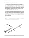
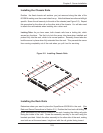
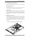
Installing the Chassis Rails
Position the fi xed chassis rail sections you just removed along the side of the
6015B-Ni making sure the screw holes line up. Note that these two rails are left/right
specifi c. Screw the rail securely to the side of the chassis (see Figure 2-2). Repeat
this procedure for the other rail on the other side of the chassis. You will also need
to attach the rail brackets when installng into a telco rack.
Locking Tabs: As you have seen, both chassis rails have a locking tab, which
serves two functions. The fi rst is to lock the server into place when installed and
pushed fully into the rack, which is its normal position. Secondly, these tabs also
lock the server in place when fully extended from the rack. This prevents the server
from coming completely out of the rack when you pull it out for servicing.
Figure 2-2. Installing Chassis Rails
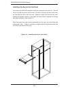
Installing the Rack Rails
Determine where you want to place the SuperServer 6015B-Ni in the rack. (See
Rack and Server Precautions in Section 2-3.) Position the fi xed rack rail/sliding rail
guide assemblies at the desired location in the rack, keeping the sliding rail guide
facing the inside of the rack. Screw the assembly securely to the rack using the
brackets provided. Attach the other assembly to the other side of the rack, making
sure both are at the exact same height and with the rail guides facing inward.