


5-8
S
UPERSERVER 6015B-Ni User's Manual
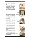
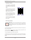
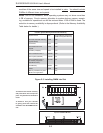
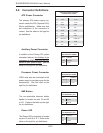
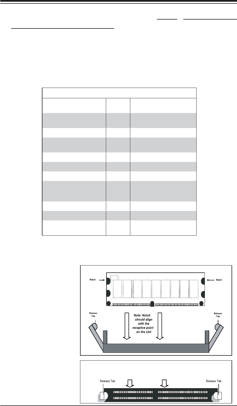
Top View of DDR2 FBD Slot
Figure 5-3. Installing DIMM into Slot
To Install: Insert module vertically
and press down until it snaps into
place. Pay attention to the bottom
notch.
To Remove: Use your thumbs
to gently push each release tab
outward to free the DIMM from the
slot.
modules of the same size and speed to be installed in pairs. You should not mix
DIMMs of different sizes and speeds.
Notes: Due to OS limitations, some operating systems may not show more than
4 GB of memory. Due to memory allocation to system devices, memory remain-
ing available for operational use will be reduced when 4 GB of RAM is used. The
reduction in memory availability is disproportional. (Refer to the Memory Availability
Table below for details.)
DDR2 FBD DIMM
Possible System Memory Allocation & Availability
System Device Size Physical Memory Remaining
(4 GB Total System Memory)
Firmware Hub fl ash memory
(System BIOS)
1 MB 3.99
Local APIC 4 KB 3.99
Area Reserved for the
chipset
2 MB 3.99
I/O APIC (4 Kbytes) 4 KB 3.99
PCI Enumeration Area 1 256 MB 3.76
PCI Express (256 MB) 256 MB 3.51
PCI Enumeration Area 2
(if needed) -Aligned on
256-MB boundary-
512 MB 3.01
VGA Memory 16 MB 2.85
TSEG 1 MB 2.84
Memory available to System
BIOS & OS applications
2.84