


Chapter 5: Advanced Serverboard Setup
5-15
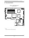
Fan Headers
The X7DWU has eight headers, des-
ignated Fan1 through Fan8. FAN7
and FAN8 are for the CPU heatsinks.
These 4-pin fan headers are for Pulse
Width Modulated (PWM) fans and
their speed is controlled via Thermal
Management with a BIOS setting.
See the tables on the right for pin
defi nitions.
Serial Ports
The COM1 serial port is located on
the IO backplane. COM2 is a header
on the serverboard (see serverboard
layout for location). See the table on
the right for pin defi nitions.
Note: Pin 10 is included on the header but not on
the port. NC indicates no connection.
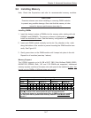
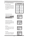
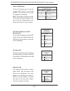
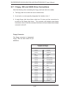
Serial Port Pin Defi nitions
(COM1, COM2)
Pin # Defi nition Pin # Defi nition
1 DCD 6 DSR
2 RXD 7 RTS
3 TXD 8 CTS
4 DTR 9 RI
5 Ground 10 NC
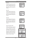
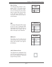
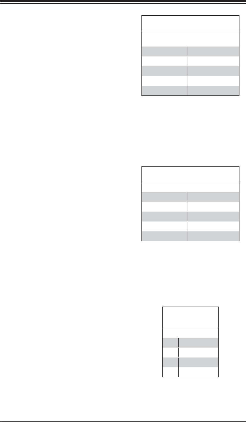
4-pin Fan Header
Pin Defi nitions
(FAN1-8)
Pin# Defi nition
1 Ground (Black)
2 +12V (Red)
3 Tachometer
4 PWM Control
Universal Serial Bus Headers
Three additional USB headers (USB2/
USB3 and USB4) are included on the
serverboard. These may be used for
front side access. A USB cable (not
included) is needed for the connec-
tion. See the table on the right for pin
defi nitions.
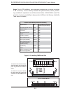
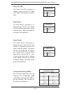
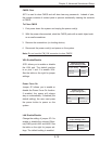
Universal Serial Bus Headers
Pin Defi nitions (USB2/3, USB4)
USB2
Pin # Defi nition
USB3, USB4
Pin # Defi nition
1 +5V 1 +5V
2 PO- 2 PO-
3 PO+ 3 PO+
4 Ground 4 Ground
5 Key 5 NC