


6-2
SUPERSERVER 6016XT-TF/6016GT-TF/TF-TM2/TF-TC2 User's Manual
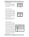
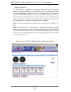
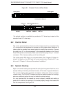
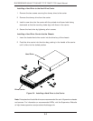
Figure 6-1. Chassis: Front and Rear Views
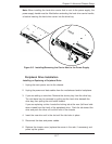
6-2 Control Panel
The control panel (located on the front of the chassis) must be connected to the
JF1 connector on the serverboard to provide you with system status indications. A
ribbon cable has bundled these wires together to simplify the connection. Connect
the cable from JF1 on the serverboard to the appropriate header on the Control
Panel PCB (printed circuit board). Make sure the red wire plugs into pin 1 on both
connectors. Pull all excess cabling out of the airfl ow path.
The control panel LEDs inform you of system status. See "Chapter 3: System In-
terface" for details on the LEDs and the control panel buttons. Details on JF1 can
be found in "Chapter 5: Advanced Serverboard Installation."
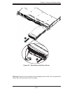
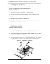
6-3 System Cooling
Eight 4-cm counter-rotating fans provide the cooling for the system. Each fan unit is
actually made up of two fans joined back-to-back, which rotate in opposite directions.
This counter-rotating action generates exceptional airfl ow and works to dampen
vibration levels. The SC818GTQ chassis provides two additional open fan housings,
where an additional system fan may be added for optimal cooling.
It is very important that the chassis top cover is properly installed and making a
good seal in order for the cooling air to circulate properly through the chassis and
cool the components. See Figure 6-2.
Control Panel
Hot-Swap Drive Bays (3)*
PCI Slot COM Port
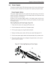
Power Supply
USB Ports
LAN Ports VGA Port
Dedicated IPMI LAN Port
*An optional solution is available to provide six 2.5" drive bays instead of the
standard three 3.5" drive bays.