


5-14
A+ SERVER 2042G-TRF/6RF User's Manual
5-9 Connector Defi nitions
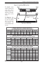
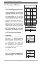
Power Connectors
A 24-pin main power supply connector(JPW1)
and three 8-pin CPU PWR connectors
(JPW2/JPW3/JPW4) on the motherboard.
These power connectors meet the SSI EPS
12V specifi cation. In addition to the 24-pin
ATX power connector, the 12V 8-pin CPU
PWR connectors at JPW2/JPW3/JPW4 must
also be connected to your power supply. See
the table on the right for pin defi nitions.
Warning: To prevent damage to the power
supply or motherboard, please use a power
supply that contains a 24-pin and three 8-pin
power connectors. Be sure to connect these
connectors to the 24-pin (JPW1) and the
three 8-pin (JPW2,JPW3 and JPW4) power
connectors on the motherboard. Failure in
doing so will void the manufacturer warranty
on your power supply and motherboard.
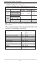
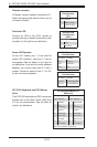
ATX Power 24-pin Connector
Pin Defi nitions
Pin# Defi nition Pin # Defi nition
13 +3.3V 1 +3.3V
14 -12V 2 +3.3V
15 COM 3 COM
16 PS_ON 4 +5V
17 COM 5 COM
18 COM 6 +5V
19 COM 7 COM
20 Res (NC) 8 PWR_OK
21 +5V 9 5VSB
22 +5V 10 +12V
23 +5V 11 +12V
24 COM 12 +3.3V
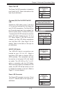
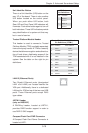
12V 8-pin PWR Connector
Pin Defi nitions
Pins Defi nition
1 through 4 Ground
5 through 8 +12V
Required Connection
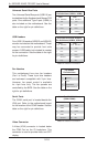
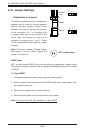
Reset Connector
The reset connector is located on pins 3 and
4 of JF1 and attaches to the reset switch on
the computer chassis. See the table on the
right for pin defi nitions.
Reset Button
Pin Defi nitions
(JF1)
Pin# Defi nition
3 Reset
4 Ground
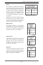
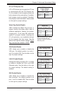
Power Button
The Power Button connection is located on
pins 1 and 2 of JF1. Momentarily contacting
both pins will power on/off the system. This
button can also be confi gured to function
as a suspend button (with a setting in the
BIOS - see Chapter 4). To turn off the power
when set to suspend mode, press the button
for at least 4 seconds. Refer to the table on
the right for pin defi nitions.
Power Button
Pin Defi nitions
(JF1)
Pin# Defi nition
1 PWR
2 Ground