


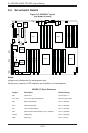

5-16
A+ SERVER 2042G-TRF/6RF User's Manual
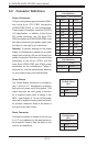
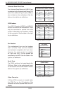
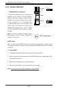
Universal Serial Bus Ports
Two Universal Serial Bus ports (USB 2.0) are
located beside the Keyboard and Mouse PS2
ports. One additional Type A port (USB6) is
also included on the motherboard. See the
table on the right for pin defi nitions.
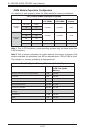
Universal Serial Bus Ports
Pin Defi nitions (USB0/1, USB6)
USB0
Pin # Defi nition
USB1
Pin # Defi nition
1 +5V 1 +5V
2 PO- 2 PO-
3 PO+ 3 PO+
4 Ground 4 Ground
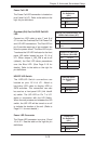
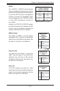
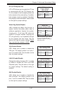
USB Headers
Four USB 2.0 headers (USB2/3 and USB4/5)
are also included on the motherboard. These
may be connected to provide front side
access. A USB cable (not included) is needed
for the connection. See the table on the right
for pin defi nitions.
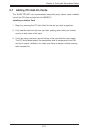
Universal Serial Bus Headers
Pin Defi nitions (USB2/3, USB4/5)
USB2
Pin # Defi nition
USB3
Pin # Defi nition
1 +5V 1 +5V
2 PO- 2 PO-
3 PO+ 3 PO+
4 Ground 4 Ground
5 Key 5 NC
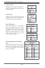
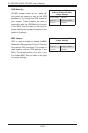
Fan Header
Pin Defi nitions
Pin# Defi nition
1 Ground
2 +12V
3 Tachometer
4 PWR Modulation
Fan Headers
This motherboard has nine fan headers
(Fan1 to Fan9). These 4-pin fans headers
are backward compatible with 3-pin fans.
However, fan speed control is available
for 4-pin fans only. The fan speeds are
controlled by the BIOS. See the table on the
right for pin defi nitions
Note: NC indicates no connection.
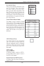
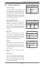
Serial Ports
The COM1 serial port is located beside the
VGA port. Refer to the motherboard layout
for the location of the COM2 header. See the
table on the right for pin defi nitions.
Note: NC indicates no connection.
Serial Port Pin Defi nitions
(COM1/COM2)
Pin # Defi nition Pin # Defi nition
1 DCD 6 DSR
2 RXD 7 RTS
3 TXD 8 CTS
4 DTR 9 RI
5 Ground 10 NC
Video Connector
A Video (VGA) connector is located below
the COM Port on the IO backplane. This
connector is used to provide video and CRT
display.