


2-20
C2SEA/C2SEE User's Manual
JL1
JI2C1
JI2C2
JOH1
JPUSB1
JPI1
JWD1
JPL1
JPAC
JLED1
JPD1
COM1
JPW1
Floopy
JPW2
JWOL1
SMBUS_PS1
DIMM1
DIMM2
CD1
JBT1
SPKR1
LE1
JD1
Fan5
Fan4
Fan1
Fan3
Fan2
LAN1
JPUSB2
DIMM2B
DIMM4
DIMM3
USB 10/11
USB 8/9
USB6
1394_2
Slot7 PCI-E x1
Slot6 PCI-E Gen2 x16
Slot3 PCI 33MHz
HD AUDIO
JWOR
CPU
CPU Fan
FP Audio
1394_1
CMOS CLEAR
C2SEA/C2SEE
IDE
VGA
HDMI
USB/0/1
I-SATA3
I-SATA2
I-SATA1
I-SATA0
Slot1 PCI 33MHz
Slot5 PCI 33MHZ
Slot4 PCI-E x4 on x16
KB/MOUSE
SPI BIOS
Slot2 PCI 33MHz
DIMM2A
DIMM1B
DIMM1A
USB7
JF1
USB2/3/4/5
SPDIF_Out
Printer
I-SATA4
I-SATA5
Battery
Intel
G45 (C2SEA)
G43 (C2SEE)
ICH10
Intel
Lan
CTRL
S I/O
IDE
CTRL
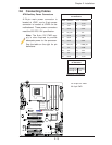
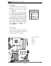
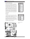
A. Front Panel Audio
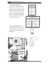
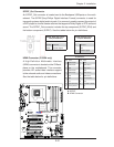
B. CD-In
CD1 Pin Defi nition
Pin# Defi nition
1 Left Stereo Signal
2 Ground
3 Ground
4 Right Stereo
Signal
CD Header
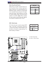
In addition to the front panel audio connector,
a 4-pin CD header is located at CD1 on the
motherboard.These headers allow you to use
the onboard sound for audio CD playback. Con-
nect an audio cable from your CD drive to the
header that fi ts your cable's connector. Only one
CD header can be used at any one time. See
the tables at right for pin defi nitions.
A
B
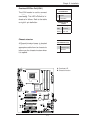
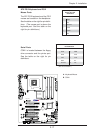
Front Panel Audio Control
When front panel headphones are plugged in,
the back panel audio output is disabled. This is
done through the FP Audio header (J12). If the
front panel interface card is not connected to
the front panel audio header, jumpers should be
installed on the header (J12) pin pairs: 1-2, 5-6,
and 9-10. If these jumpers are not installed, the
back panel line out connector will be disabled and
microphone input Pin 1 will be left fl oating, which
can lead to excessive back panel microphone
noise and cross talk. See the table below for
pin defi nitions.
FP Audio
Pin Defi nitions
Pin# Defi n.
1 MIC_L
2 AUD_GND
3 MIC_R
4 FP-Audio-Detect
5 Line_2_R
6 Ground
7 FP-Jack-Detect
8 Key
9 Line_2_L
10 Ground