


Chapter 2: Installation
2-13
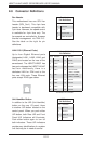
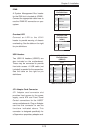
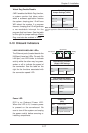
Overheat LED
Connect an LED to the JOH1
header to provide warning of chassis
overheating. See the table on the right
for pin defi nitions.
Overheat LED
Pin Defi nitions
(JOH1)
Pin# Defi nition
1 3.3V
2 OH Active
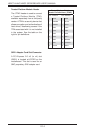
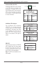
IPMB
A System Management Bus header
for the IPMI slot is located at JIPMB1.
Connect the appropriate cable here to
use the IPMB I2C connection on your
system.
JIPMB1
Pin Defi nitions
Pin# Defi nition
1 Data
2 Ground
3 Clock
4 No Connection
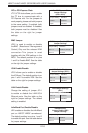
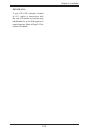
USB Headers
Two USB 2.0 headers (USB2/3) are
also included on the motherboard.
These may be connected to provide
front side access. A USB cable (not
included) is needed for the connection.
See the table on the right for pin
defi nitions.
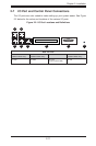
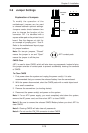
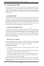
JP1 Adapter Card Connector
JP1 Adapter card connector slot
provides front access to the power
supply, serial ATA and Front Panel
Control connections for the H8DCT
series motherboards. Plug an Adapter
card into this connector to use the
functions indicated above. This
connector is designed specifi cally for
a Supermicro-proprietary adapter card.
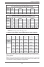
Universal Serial Bus Headers
Pin Defi nitions
(USB2/3)
JUSB1
Pin# Defi nition Pin# Defi nition
1 +5V 2 +5V
3 PO- 4 PO-
5 PO+ 6 PO+
7 Ground 8 Ground
9 Key 10 NC
Note: NC indicates no connection.