


1-4
H8QM8-2/H8QME-2 User’s Manual
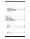
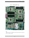
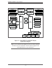
Notes:
1. Jumpers not indicated are for test purposes only.
2. The H8QME-2 has the same layout as the H8QM8-2 but with no SCSI compo-
nents, connectors or jumpers.
3. The silkscreen on the motherboard noting CPU3 and CPU4 have been reversed
on PCB revisions 2.01 and later. Since you must install either two or four CPUs, this
change has no affect on the board's functionality.
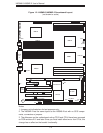
Figure 1-2. H8QM8-2/H8QME-2 Serverboard Layout
(not drawn to scale)
SUPER H8QM8-2
DIMMD 2A
BIOS
JF1
JA2: SCSI CH B
IDE#1
ATI
ES 1000
Kybd/
Mouse
Battery
JBT1
AIC-7902W
JLAN1
JLAN2
Parallel
Port
USB0/1
COM1
VGA
CPU 3
CPU 2
CPU 1
CPU 4
Slot #1: 100 MHz PCI-X (ZCR)
Slot #2: 100 MHz PCI-X
Slot #3: 133/100 MHz PCI-X
Slot #4: 133/100 MHz PCI-X
Slot #5: PCI-Express x8
Slot #6: PCI-Express x16 HT Connector
Floppy
JA1: SCSI CH A
JPW2
JPW1
J1B1
nVidia MCP55 Pro
AMD-8132
DIMMD 2B
DIMMD 1A
DIMMD 1B
DIMMC 1B
DIMMC 1A
DIMMC 2B
DIMMC 2A
DIMMA 2A
DIMMA 2B
DIMMA 1A
DIMMA 1B
DIMMB 1B
DIMMB 1A
DIMMB 2B
DIMMB 2A
JF2
N-SATA5N-SATA4N-SATA2N-SATA0
N-SATA3N-SATA1
COM2
HT Connector
FAN9
FAN8/CPU4
JPL1
JI
2
C4
JI
2
C3
JPXA1/JPXB1
nFAN2
nFAN1
JWD
JUSB2/3
JI
2
C2
JI
2
C1
JPA2
PS_SMBUS
J3P
JPA3/JL1
JPA1
JP1
JWOR
JWF1
SGPIO2
SGPIO1
FAN6
FAN4/CPU1
FAN3/CPU2
FAN2
FAN1
FAN5
SIMSO
FAN7/CPU3
JAR
JOH1
JPG1
JWOL
J4
DP2
Speaker