


2-14
H8QM8-2/H8QME-2 User's Manual
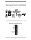
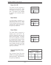
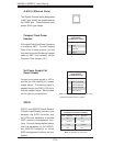
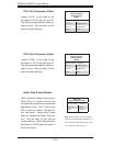
Compact Flash Power
Headers
A Compact Flash Card Power Connector
is located at JWF1. For the Compact
Flash Card to work properly, you will
fi rst need to connect the device's power
cable to JWF1 and correctly set the
Compact Flash Jumper (JP1).
Compact Flash
Power Header
Pin Defi nitions (JWF1)
Pin# Defi nition
1 +5V
2 Ground
3 Signal
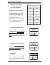
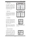
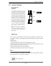
3rd Power Supply Fail
Detect Header
Connect your power supply to J3P to
provide you with warning of a power
supply failure. The warning signal is
passed through the PWR_LED pin to
indicate a power failure. See the table
on the right for pin defi nitions.
3rd Power Supply Fail
Detect Header
Pin Defi nitions (J3P)
Pin# Defi nition
1 P/S 1 Fail Signal
2 P/S 2 Fail Signal
3 P/S 3 Fail Signal
4 Alarm Reset
Note: This feature is only available when using
redundant Supermicro power supplies.
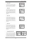
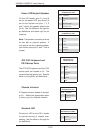
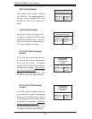
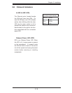
SGPIO
SGPIO1 and SGPIO2 (Serial General
Purpose Input/Output) provide a bus
between the SATA controller and
the SATA drive backplane to provide
SATA enclosure management func-
tions. Connect the appropriate cables
from the backplane to the SGPIO1
and SGPIO2 header(s) to utilize
SATA management functions on your
system.
SGPIO Header
Pin Defi nitions (SGPIO1, SGPIO2)
Pin# Defi nition Pin # Defi nition
1NC 2NC
3 Ground 4 Data
5 Load 6 Ground
7NC 8NC
Note: NC indicates no connection.
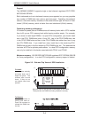
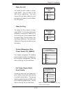
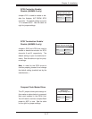
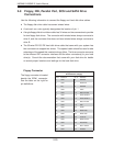
JLAN1/2 (Ethernet Ports)
Two Gigabit Ethernet ports (designated
JLAN1 and JLAN2) are located beside
the COM2 port. These Ethernet ports
accept RJ45 type cables.