


H8QM8-2/H8QME-2 User’s Manual
iv
Table of Contents
Chapter 1: Introduction
1-1 Overview ......................................................................................................... 1-1
Checklist ................................................................................................... 1-1
Contacting Supermicro ............................................................................. 1-2
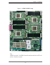
H8QM8-2/H8QME-2 Image ...................................................................... 1-3
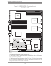
H8QM8-2/H8QME-2 Serverboard Layout ................................................ 1-4
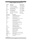
H8QM8-2/H8QME-2 Quick Reference ..................................................... 1-5
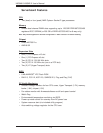
Serverboard Features .............................................................................. 1-6
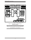
nVidia MCP55 Pro/AMD-8132 Chipset: System Block Diagram ............. 1-8
1-2 Chipset Overview ........................................................................................... 1-9
1-3 PC Health Monitoring ................................................................................... 1-10
1-4 Power Confi guration Settings ....................................................................... 1-11
1-5 Power Supply ............................................................................................... 1-12
1-6 Super I/O ....................................................................................................... 1-13
Chapter 2: Installation
2-1 Static-Sensitive Devices ................................................................................. 2-1
2-2 Processor and Heatsink Installation ............................................................... 2-2
2-3 Mounting the Serverboard into a Chassis ...................................................... 2-5
2-4 Installing Memory ........................................................................................... 2-5
2-5 I/O Port and Control Panel Connections ........................................................ 2-7
2-6 Connecting Cables ......................................................................................... 2-8
ATX Power Connector .............................................................................. 2-8
Processor Power Connector .................................................................... 2-8
NMI Button ............................................................................................... 2-8
Power LED ............................................................................................... 2-9
HDD LED ................................................................................................ 2-9
NIC1 LED ................................................................................................. 2-9
NIC2 LED ................................................................................................. 2-9
Overheat/Fan Fail LED ............................................................................ 2-9
Power Fail LED ...................................................................................... 2-10
Reset Button .......................................................................................... 2-10
Power Button .......................................................................................... 2-10
Universal Serial Bus Ports ..................................................................... 2-10
USB Headers ......................................................................................... 2-11
Serial Port .............................................................................................. 2-11