


2-12
H8QM3-2/H8QMi-2 User's Manual
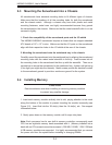
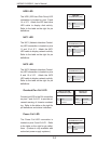
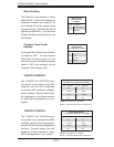
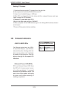
Wake-On-Ring
The Wake-On-Ring header is desig-
nated JWOR. This function allows your
computer to receive and "wake-up" by
an incoming call to the modem when
in suspend state. See the table on the
right for pin defi nitions. You must have
a Wake-On-Ring card and cable to use
this feature.
Wake-On-Ring
Pin Defi nitions
(JWOR)
Pin# Defi nition
1 Ground (Black)
2 Wake-up
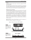
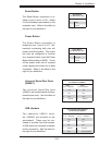
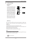
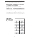
Compact Flash Power
Headers
A Compact Flash Card Power Connector
is located at JWF1. For the Compact
Flash Card to work properly, you will
fi rst need to connect the device's power
cable to JWF1 and correctly set the
Compact Flash Jumper (JP1).
Compact Flash
Power Header
Pin Defi nitions (JWF1)
Pin# Defi nition
1 +5V
2 Ground
3 Signal
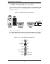
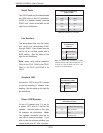
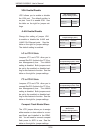
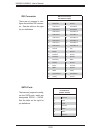
3-SGPIO1/3-SGPIO2
The 3-SGPIO1 and 3-SGPIO2 head-
ers provide a bus between the SAS
controller and the drive backplane
to provide SAS enclosure manage-
ment functions. Connect cables from
the backplane to the these headers
to utilize SAS management on your
system.
SAS SGPIO Headers
Pin Defi nitions (3-SGPIO1, 3-SGPIO2)
Pin# Defi nition Pin # Defi nition
1NC 2NC
3 Ground 4 Data
5 Load 6 Ground
7NC 8NC
Notes: NC indicates no connection.
SGPIO = Serial General Purpose Input/Output
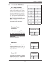
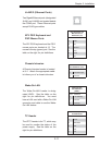
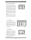
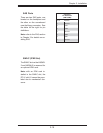
T-SGPIO1/T-SGPIO2
The T-SGPIO1 and T-SGPIO2 head-
ers provide a bus between the SATA
controller and the drive backplane to
provide SATA enclosure management
functions. Connect cables from the
backplane to these headers to utilize
SATA management on your system.
SATA SGPIO Headers
Pin Defi nitions (T-SGPIO1, T-SGPIO2)
Pin# Defi nition Pin # Defi nition
1NC 2NC
3 Ground 4 Data
5 Load 6 Ground
7NC 8NC
Notes: NC indicates no connection.
SGPIO = Serial General Purpose Input/Output