


2-12
SUPER P3TDDR User’s Manual
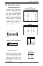
2-7 Jumper Settings
Explanation of
Jumpers
To modify the operation of the
motherboard, jumpers can be used
to choose between optional set-
tings. Jumpers create shorts be-
tween two pins to change the
function of the connector. Pin 1 is
identified with a square solder pad
on the printed circuit board.
On a 2-pin jumper, "Closed" means
the jumper is over both pins (to
"close" the connection) and
"Open" means the jumper is either
off or on a single pin only. See
the motherboard layout pages for
jumper locations.
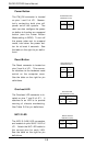
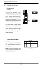
Connector
Pins
Jumper
Cap
Setting
Pin 1-2 short
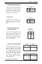
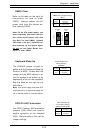
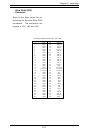
Front Side Bus Speed
The FSB speed (also known as
system speed) is set with JP6 and
JP7. See the table on the right for
pin definitions.
Note: Most Intel processors have
a fixed speed that overrules the
setting of JP6 and JP7.
3 2 1
3 2 1
Front Side Bus Speed Jumper Settings
(JP6, JP7)
JP6
1-2
2-3
Open
JP7
1-2
2-3
Open
FSB Speed
Auto
66 MHz
100 MHz
133 MHz
Note: The Auto setting allows the CPU
to set the speed.
Open2-3