


P8SC8/P8SCi User’s Manual
Table of Contents
Preface
About This Manual ...................................................................................................... iii
Manual Organization ................................................................................................... iii
Chapter 1: Introduction
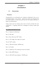
1-1 Overview......................................................................................................... 1-1
Checklist .................................................................................................... 1-1
Contacting Supermicro............................................................................ 1-2
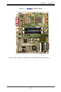
SUPER P8SC8 Image ................................................................ 1-3
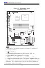
P8SC8/P8SCi Layout ................................................................ 1-4
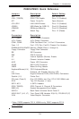
P8SC8/P8SCi Quick Reference ............................................... 1-5
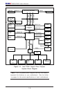
E7221 Chipset: System Block Diagram ................................................. 1-6
Motherboard Features ............................................................................ 1-7
1-2 Chipset Overview........................................................................................... 1-9
1-3 PC Health Monitoring.................................................................................... 1-10
1-4 CPU Thermal Management .......................................................................... 1-10
1-5 Power Configuration Settings .................................................................... 1-11
1-6 Power Supply ............................................................................................... 1-12
1-6 Super I/O......................................................................................................... 1-13
Chapter 2: Installation
2-1 Static-Sensitive Devices ............................................................................... 2-1
2-2 Processor and Heatsink Installation............................................................ 2-2
2-3 Mounting the Motherboard in the Chassis ................................................. 2-5
2-4 Installing DDR2 Memory................................................................................. 2-6
2-5 I/O Port/Front Control Panel Connector Locations.................................... 2-7
2-6 Connecting Cables ......................................................................................... 2-8
Power Supply Connectors ..................................................................... 2-8
PW_ON Connector ................................................................................... 2-8
Reset Connector ....................................................................................... 2-9
Overheat/Fan Fail LED ............................................................................ 2-9
NIC1/NIC2 LED Indicators....................................................................... 2-10
IDE/SATA LED ........................................................................................ 2-10
Power On_LED Connector .................................................................... 2-11
NMI Button ............................................................................................... 2-11
Serial Ports .............................................................................................. 2-12
Speaker Connector................................................................................ 2-12
iv