


5-11
Chapter 5: BIOS
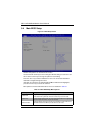
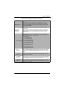
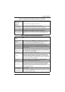
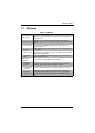
Serial Port 2
Configuration
submenu
This submenu allows you to configure Serial Port 2.
Serial Port This setting allows you to Enable or Disable the Serial Port.
Device Settings This static display shows device settings for serial port 2 configuration.
Change Settings
Use this setting to select an optimal setting for the Super IO device to use for the
Serial Port. Options include Auto, IO=3F8h/IRQ=4, IO=3F8h/IRQ=3~12,
IO=2F8h/IRQ=3~12, IO=3E8h/IRQ=3~12 and IO=2E8h/IRQ=3~12
Serial Port Mode
This setting allows you to set the Serial Port Mode to either Normal or High
Speed.
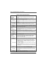
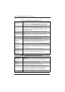
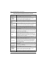
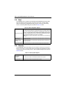
Table 5-9. Serial Port Console Redirection Sub-menu
Menu Option Description
COM1
Console Redirection Use this setting to Enable or Disable Console Redirection for the COM1 port.
Console
Redirection Settings
This submenu contains Console Redirection settings for the COM1 port. This
menu is only available when Console Redirection is enabled.
Terminal Type
This setting allows you to select the Terminal Type to use for Console
Redirection emulation. Options include ANSI (extended ASCII character set),
VT100 (ASCII character set), VT100+ (extends VT100 to support color, function
keys, etc.) and VT-UTF8 (uses UTF8 encoding to map Unicode characters onto
one or more bytes).
Bits per Second
This setting selects the serial port transmission speed, which must be matched
on the other side. Long or noisy lines may require lower speeds. Options include
9600, 19200, 38400, 57600 and 115200.
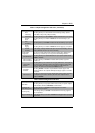
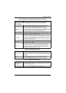
Data Bits This sets the number of data bits as either 7 or 8.
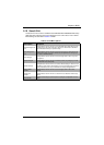
Parity
A parity bit can be sent with the data bits to detect some transmission errors.
Options include None (no parity bit), Even (parity bit is 0 if the number of 1’s in
the data bits is even), Odd (parity bit is 0 if the number of 1’s in the data bits is
odd), Mark (parity bit is always 1) or Space (parity bit is always 0. The Mark and
Space Parity do not allow for error detection.
Stop Bits
Stop bits indicate the end of a serial data packet (a start bit indicates the
beginning). The standard setting is 1 stop bit. Communications with slow devices
may require more than 1 stop bit. Options are 1 or 2.
Flow Control
Flow control can prevent data loss from buffer overflow. When sending data, if
the receiving buffers are full, a ‘stop’ signal can be sent to stop the data flow.
Once the buffers are empty, a ‘start’ signal can be sent to re-start the flow.
Hardware flow control uses two wires to send start/stop signals. Options include
None and Hardware RTS/CTS.
VT-UTF8 Combo
Key Support
This setting Enables or Disables VT-UTF8 Combination Key support for ANSI/
VT100 terminals.
Recorder Mode
This setting Enables or Disables Recorder Mode. When enabled only text will be
sent. This is to capture Terminal data.
Table 5-8. SuperIO Device Configuration Sub-menu (Continued)
Menu Option Description