


SCF418 Chassis Manual
4-2
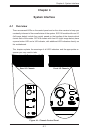
4-2 Control Panel Buttons
•Power: The main power button on each of the four control panels is
used to apply or remove power from the power supply to each of the
four systems in the chassis. Turning off system power with this but-
ton removes the main power, but keeps standby power supplied to the
system. Therefore, you must unplug system before servicing. The poer
button has a built-in LED which will turn green when the power is on.
•UID: When used with a UID compatible motherboard, the UID indicator is used
to turn on or off the blue light function of the LED. This is built into the front
side of the UID button and at the rear end of each motherboard node, for those
motherboards which support it. Once the blue light is activated, the unit can be
easily located in very large racks and server banks.
4-3 Control Panel LEDs
The four control panels are located on the front handle of the SCF418 chassis.
Each control panel has two additional LEDs. These LEDs provide you with critical
information related to different parts of the system. This section explains what each
LED indicates when illuminated and any corrective action you may need to take.
•Informational LED:
Continuously on and blue: UID function has been activated.
Flashing red: Fan failure.
Continuously on and red: Overheat condition. This may be caused by cables
obstructing the airow in the system or the ambient room temperature being
too warm. Check the routing of the cables and make sure all fans are present
and operating normally. You should also check to make sure that the chassis
covers are installed. Finally, verify that the heatsinks are installed properly.
This LED will remain ashing or on as long as the overheat or fan failure
condition exists.