


Chapter 2: Installation
2-21
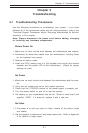
2-9 Parallel Port, Floppy/Hard Disk Drive and SCSI
Connections
Note the following when connecting the floppy and hard disk drive cables:
• The floppy disk drive cable has seven twisted wires.
• A red mark on a wire typically designates the location of pin 1.
• A single floppy disk drive ribbon cable has 34 wires and two connectors to
provide for two floppy disk drives. The connector with twisted wires always
connects to drive A, and the connector that does not have twisted wires
always connects to drive B.
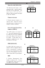
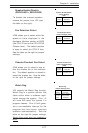
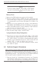
Parallel Port Connector
The parallel port is located on J65.
See the table below right for pin
definitions.
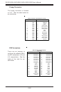
Pin Number Function
1 Strobe-
3 Data Bit 0
5 Data Bit 1
7 Data Bit 2
9 Data Bit 3
11 Data Bit 4
13 Data Bit 5
15 Data Bit 6
17 Data Bit 7
19 ACK
21 BUSY
23 PE
25 SLCT
Pin Number Function
2 Auto Feed-
4 Error-
6 Init-
8 SLCT IN-
10 GND
12 GND
14 GND
16 GND
18 GND
20 GND
22 GND
24 GND
26 NC
Parallel (Printer) Port Pin Definitions
(J65)
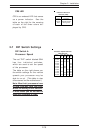
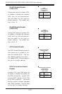
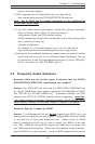
Main Power Override
(X5DL8-GG)
Instead of using the chassis
power on switch, you may close
jumper JP7 to apply power to the
system. This effectively disables
the power button from turning off
the system. See the table on the
right for jumper settings. The de-
fault setting is Open (normal).
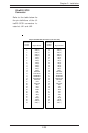
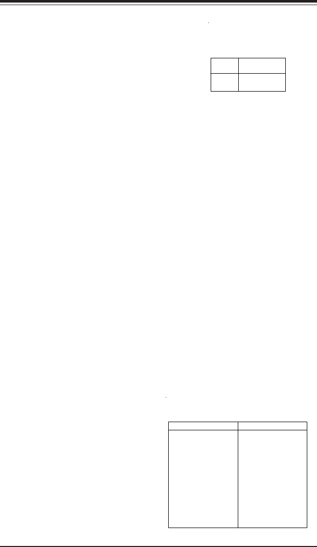
Jumper
Position
Open
Closed
Definition
Normal
Force Power On
Power On
Jumper Settings
(JP1)