


Chapter 2: Installation
2-11
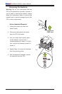
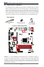
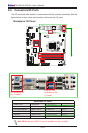
X10SLQ (-L)
Rev. 1.00
MAC CODE
BAR CODE
BIOS
LICENSE
JSD1
JBT1
SP1
JITP1
LED1
LED2
LED3
T-SGPIO1
T-SGPIO2
COM1
COM2
COM3
COM4
JD1
FAN3
FAN2
FAN1
FAN4
JP2
JP1
JLED1
JWD1
JPL2
JPL1
JPAC1
JI2C1 JI2C2
JP5
JP4
JP3
JL1
JWOR1
JHD_AC1
I-SATA2
I-SATA1
I-SATA3
I-SATA0
I-SATA4
JTPM1
JF1
JPW2
USB10/11(3.0)
AUDIO FP
USB6/7
USB8/9
SLOT4 PCI-E 2.0 X4
SLOT5 PCI-E 2.0 X1
HD AUDIO
SLOT7 PCI-E 3.0 X16
USB4/5
LAN2
USB2/3(3.0)
LAN1
HDMI/DP
ALWAYS POPULATE BLUE SOCKET FIRST
UNB NON-ECC DDR3 DIMM REQUIRED
VGA/DVI
KB/MOUSE
USB0/1
CPU FAN
DIMMA1
DIMMA2
DIMMB1
DIMMB2
Battery
JPW1
BIOS
Intel PCH
JBR1
JPME1
JVR1
Not On “-L
Model”
Not On “-L Model”
Not On “-L Model”
Not On “-L
Model”
CPU
Not On “-L Model”
Not On “-L Model”
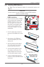
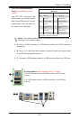
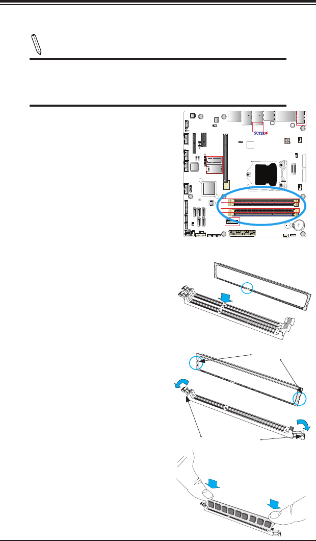
2-4 Installing DDR3 Memory
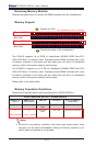
Note: Check the Supermicro website for recommended memory mod-
ules.
CAUTION
Exercise extreme care when installing or removing DIMM modules to
prevent any possible damage.
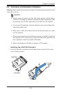
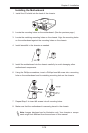
DIMM Installation
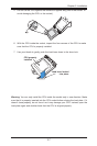
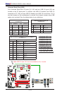
1. Insert the desired number of DIMMs
into the memory slots, starting with
DIMMA2 (Channel A, Slot 2, see
the next page for the location). For
the system to work properly, please
use the memory modules of the
same type and speed in the same
motherboard.
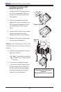
Release Tabs
Notches
2. Push the release tabs outwards on
both ends of the DIMM slot to unlock
it.
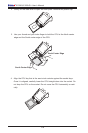
Press both notches
straight down into
the memory slot.
3. Align the key of the DIMM mod-
ule with the receptive point on the
memory slot.
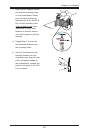
4. Align the notches on both ends of
the module against the receptive
points on the ends of the slot.
5. Use two thumbs together to press
the notches on both ends of the
module straight down into the slot
until the module snaps into place.
6. Press the release tabs to the lock
positions to secure the DIMM module
into the slot.