


2-22
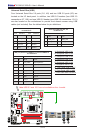
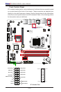
X10SLQ/X10SLQ-L User’s Manual
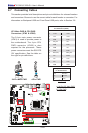
X10SLQ (-L)
Rev. 1.00
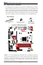
MAC CODE
BAR CODE
BIOS
LICENSE
JSD1
JBT1
SP1
JITP1
LED1
LED2
LED3
T-SGPIO1
T-SGPIO2
COM1
COM2
COM3
COM4
JD1
FAN3
FAN2
FAN1
FAN4
JP2
JP1
JLED1
JWD1
JPL2
JPL1
JPAC1
JI2C1 JI2C2
JP5
JP4
JP3
JL1
JWOR1
JHD_AC1
I-SATA2
I-SATA1
I-SATA3
I-SATA0
I-SATA4
JTPM1
JF1
JPW2
USB10/11(3.0)
AUDIO FP
USB6/7
USB8/9
SLOT4 PCI-E 2.0 X4
SLOT5 PCI-E 2.0 X1
HD AUDIO
SLOT7 PCI-E 3.0 X16
USB4/5
LAN2
USB2/3(3.0)
LAN1
HDMI/DP
ALWAYS POPULATE BLUE SOCKET FIRST
UNB NON-ECC DDR3 DIMM REQUIRED
VGA/DVI
KB/MOUSE
USB0/1
CPU FAN
DIMMA1
DIMMA2
DIMMB1
DIMMB2
Battery
JPW1
BIOS
Intel PCH
JBR1
JPME1
JVR1
Not On “-L
Model”
Not On “-L Model”
Not On “-L Model”
Not On “-L
Model”
CPU
Not On “-L Model”
Not On “-L Model”
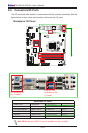
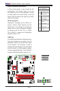
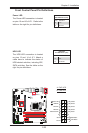
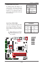
Front Control Panel
JF1 contains header pins for various buttons and indicators that are normally located
on a control panel at the front of the chassis. These connectors are designed spe-
cically for use with Supermicro chassis. See the gure below for the descriptions
of the front control panel buttons and LED indicators. Refer to the following section
for descriptions and pin denitions.
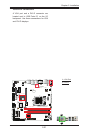
Pin 15Pin 16
Pin 1
Pin 2
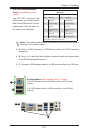
JF1 Header Pins
Power Button
OH/Fan Fail
LED
1
NIC1 LED
Reset Button
2
HDD LED
Power LED
Reset
PWR
LED_Anode+
LED_Anode+
LED_Anode+
LED_Anode+
Ground
Ground
X
X
NIC2 LED
LED_Anode+