


Chapter 2: Installation
2-19
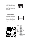
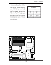
LAN1
®
JLAN1
S
UPER X6DH3-G2
LAN2
DIMM 2
A
DIMM 2B
DIMM 3A
DIMM 3B
DIMM 4A
DIMM 4B
DIMM 1B
DIM
M 1
A
12V 8-pin
PWR
JF1
FP Control
JOH
IPMI
IDE2
Floppy
BIOS
Fan4
SMB
PCI-X100
MHz
P
C
I-
X 100 MHz ZCR (Gree
n
Slot)
P
CI-X 133 MHz
Battery
JPL1
PCI-E X8
VGA
COM1
US
B
0
/1
KB/MS
F
an6
F
an5
ATX PWR
12V 4-Pin
PWR
Parrallel
Port
24-Pin
Fan
7
JPW1
F
a
n8
C
PU1
S I/O
PSF
Fan3
IDE1
PCI-33 MH
z
USB2/
3
I
CH
JPG1
JWD
Slot1
Slot2
Slot3
Slot4
Slo
t5
Slot6
P
CI-E X8
GLAN
CTRL
6300ESB
B
u
zzer
PXH
JBT1
I-SAT
A1
G
LAN
CT
RL
JPL2
J
L1
J
P
S
1
SAS
CTRL
F
an2
Fan1
J
AR
J
3P
C
PU2
E752
0
B
ank1
B
ank
2
B
ank
3
Bank4
WOL
SEPC
COM2
S
MB PS
JWOR
JS10
VGA
CT
RL
JD1
J
I
2
C2
I-
SATA0
DS5
DS6
DS7
DS8
DS1
DS2
DS3
DS4
SAS4-7
SAS0-3
JSM1
JS
9
J
P9
J1D1
J32
J
38
J
33
J14
J
7
JLAN1
J
LAN2
JI
2
C
1
J31
JSM2
JP1
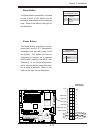
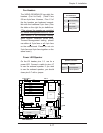
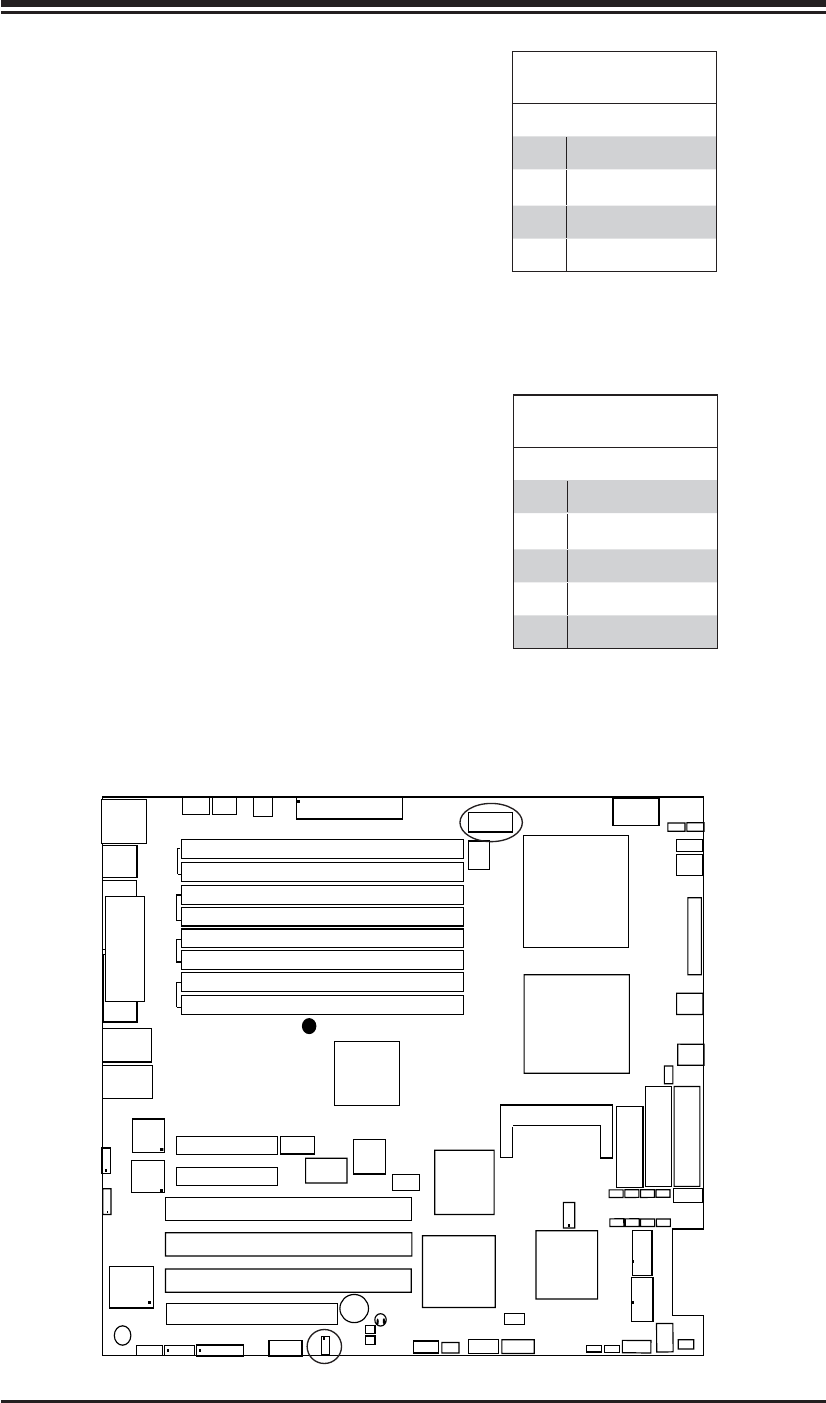
SMB
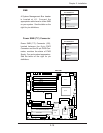
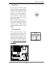
A System Management Bus header
is located at J11. Connect the
appropriate cable here to utilize SMB
on your system. See the table on the
right for pin defi nitions.
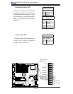
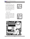
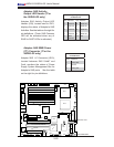
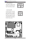
Power SMB (I
2
C) Connector
Power SMB (I
2
C) Connector (J32),
located between the 8-pin PWR
Connector and the 24-pin PWR Con-
nector, monitors the status of PWR
Supply, Fan and system temperature.
See the table on the right for pin
defi nitions.
SMB
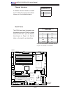
PWR SMB
PWR SMB
Pin Defi nitions
Pin# Defi nition
1 Clock
2 Data
3 PWR Fail
4 Ground
5 +3.3V
SMB Header
Pin Defi nitions
Pin# Defi nition
1 Data
2 Ground
3 Clock
4 No Connection