


2-24
X6DH3-G2/X6DHi-G2 User's Manual
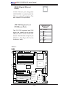
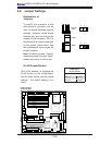
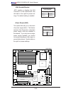
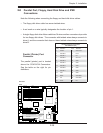
VGA Enable/Disable
JPG1 enables or disables the VGA
Connector on the motherboard. See
the table on the right for jumper set-
tings. The default setting is enabled.
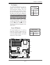
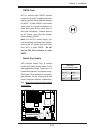
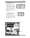
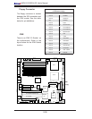
Alarm Reset (JAR)
The system will notify you in the event
of a power supply failure. This feature
assumes that Supermicro redundant
power supply units are installed in
the chassis. If you only have a single
power supply installed, you should
not connect anything to this jumper to
prevent false alarms. See the table on
the right for jumper settings.
VGA Enable
Alarm Reset
LAN1
®
JLAN1
S
UPER X6DH3-G2
LAN2
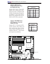
DIMM 2A
DIMM 2B
DIMM 3A
DIMM 3B
DIM
M 4A
DIMM 4B
DIM
M 1B
DIM
M 1A
12V 8-pin
PWR
JF1
FP Control
JOH
IPMI
IDE2
Flo
ppy
BIOS
Fan4
S
MB
PCI-X100 MHz
P
CI-X 100 MHz ZCR (Green Slo
t)
PCI-X 133 M
H
z
Battery
JPL1
PCI-E X8
VGA
COM1
USB
0/1
K
B/
M
S
Fan6
Fan5
A
TX PWR
12V 4-Pin
PWR
Parrallel
Port
24-Pin
Fan
7
JPW1
Fan8
CPU1
S
I
/
O
PSF
Fan3
IDE1
P
CI-3
3 MHz
USB2
/3
I
CH
JP
G1
JWD
Slot1
Slot2
Slot3
Slo
t4
Slot5
Slot6
PC
I-E X8
GLAN
C
TRL
6
300ESB
B
uzzer
PXH
J
BT1
I-
S
AT
A1
GLAN
C
T
RL
JPL2
JL1
JP
S1
SA
S
C
TRL
F
an2
Fan1
JAR
J3P
CPU2
E7520
Bank1
Bank2
Bank3
Bank4
WOL
SEPC
CO
M2
SMB PS
JWOR
JS10
VGA
CTRL
JD1
JI
2
C
2
I-SATA0
DS5
DS6
DS7
DS8
DS1
DS2
DS3
DS4
SAS4-7
SAS0-3
JSM1
JS9
JP9
J1D1
J32
J38
J33
J14
J7
JLAN1
JLAN2
JI
2
C
1
J31
JSM2
JP1
VGA Enable/Disable
Jumper Settings
Jumper Setting Defi nition
Pins 1-2 Enabled
Pins 2-3 Disabled
Alarm Reset
Jumper Settings
Pin# Defi nition
2 +5V
1 Ground