


2-12
X7SPA and X7SPE Motherboard Series User's Manual
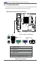
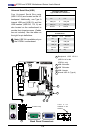
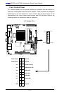
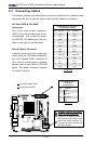
MH2
MH3MH4
D17
JPW1
JUSB1
JD1
JPC3
JPUSB1
JWD1
JPG1
JBMC1
JPL1
JPT1
JPL2
JDIMM2
1
JDIMM1
JI2C2
JI2C1
JOH1
JL1
JL2
SP1
+
J2
J3
JBT1
JBAT1
JPCIE1
JUSB5
JUSB4
JUSB3
JUSB2
JLPC80
R1050
JSMB1
FAN1 FAN2
JCOM2
JCOM4
JPI2C1
JWF1
J8
JVGA1
CD1
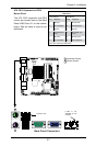
JPB
FAN
FAN
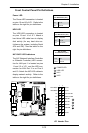
COMS CLEAR
2-3 DISABLE
1-2 ENABLE
JPB:BMC ENABLE/DISABLE
CD-in
JPT1:TPM ENABLE/DISABLE
1-2 ENABLE
2-3 DISABLE
AUDIO FP
T-SGPIO2
T-SGPIO1
JPI2C:PWR I2C
JSMB1:SMBus1
JPUSB1:USB WAKE UP
2-3 DISABLE
1-2 ENABLE
JWF1:DOM PWR
JD1:1-3 PWR LED
4-7 SPEAKER
ON:ENABLEJI2C2
OFF:DISABLE
JI2C1
OFF:DISABLE
ON:ENABLE
JL2:AUDIO FRONT PANEL SELECT
ON:AC'97 FRONT PANEL
OFF:HD AUDIO FRONT PANEL
JPG1:VGA
2-3 DISABLE
1-2 ENABLE
2-3 DISABLE
JPL2:1-2 ENABLE
JPL1:1-2 ENABLE
2-3 DISABLE
JL1:CHASISS INTRUSION
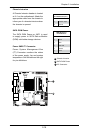
JF1 PWR ON RST X OH/FF NIC2 NIC1 HDD LED PWR LED X NMI
2-3 NMI
JWD1:1-2 RST
JBT1:
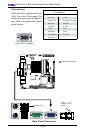
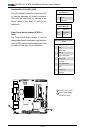
LAN2
LAN1
I-SATA5
I-SATA2
I-SATA4
I-SATA1
I-SATA3
I-SATA0
SLOT1 PCI-E X4 (IN X16 SLOT)
SYS
CPU
KB/MOUSE
COM4
COM3
COM2
COM1
SODIMM2
SODIMM1
CPU
J6
J5
J10
J11
J12
J13
J14
JPF
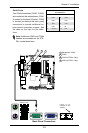
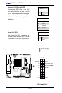
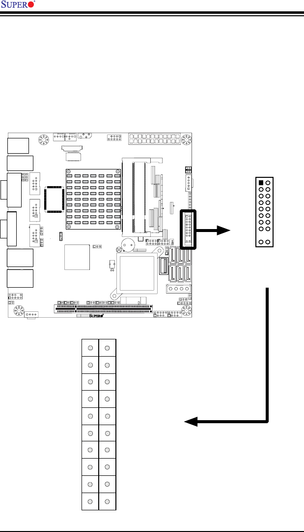
Front Control Panel
JF1 contains header pins for various buttons and indicators that are normally lo-
cated on a control panel at the front of the chassis. These connectors are designed
specically for use with Supermicro server chassis. See the gure below for the
descriptions of the various control panel buttons and LED indicators. Refer to the
following section for descriptions and pin denitions.
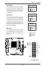
JF1 Header Pins
Power Button
OH/Fan Fail LED
1
NIC1 LED
Reset Button
2
HDD LED
Power LED
Vcc
Vcc
Vcc
Vcc
Ground
Ground
19 20
Vcc
X
Ground
NMI
X
Vcc
NIC2 LED
Power Fail LED
Pin 19
Pin 20
Pin 1
Pin 2