


Chapter 2: Installation
2-19
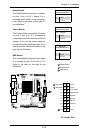
MH2
MH3MH4
D17
JPW1
JUSB1
JD1
JPC3
JPUSB1
JWD1
JPG1
JBMC1
JPL1
JPT1
JPL2
JDIMM2
1
JDIMM1
JI2C2
JI2C1
JOH1
JL1
JL2
SP1
+
J2
J3
JBT1
JBAT1
JPCIE1
JUSB5
JUSB4
JUSB3
JUSB2
JLPC80
R1050
JSMB1
FAN1 FAN2
JCOM2
JCOM4
JPI2C1
JWF1
J8
JVGA1
CD1
JPB
FAN
FAN
COMS CLEAR
2-3 DISABLE
1-2 ENABLE
JPB:BMC ENABLE/DISABLE
CD-in
JPT1:TPM ENABLE/DISABLE
1-2 ENABLE
2-3 DISABLE
AUDIO FP
T-SGPIO2
T-SGPIO1
JPI2C:PWR I2C
JSMB1:SMBus1
JPUSB1:USB WAKE UP
2-3 DISABLE
1-2 ENABLE
JWF1:DOM PWR
JD1:1-3 PWR LED
4-7 SPEAKER
ON:ENABLEJI2C2
OFF:DISABLE
JI2C1
OFF:DISABLE
ON:ENABLE
JL2:AUDIO FRONT PANEL SELECT
ON:AC'97 FRONT PANEL
OFF:HD AUDIO FRONT PANEL
JPG1:VGA
2-3 DISABLE
1-2 ENABLE
2-3 DISABLE
JPL2:1-2 ENABLE
JPL1:1-2 ENABLE
2-3 DISABLE
JL1:CHASISS INTRUSION
JF1 PWR ON RST X OH/FF NIC2 NIC1 HDD LED PWR LED X NMI
2-3 NMI
JWD1:1-2 RST
JBT1:
LAN2
LAN1
I-SATA5
I-SATA2
I-SATA4
I-SATA1
I-SATA3
I-SATA0
SLOT1 PCI-E X4 (IN X16 SLOT)
SYS
CPU
KB/MOUSE
COM4
COM3
COM2
COM1
SODIMM2
SODIMM1
CPU
J6
J5
J10
J11
J12
J13
J14
JPF
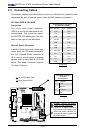
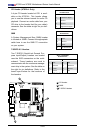
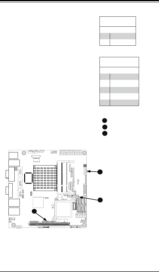
Chassis Intrusion
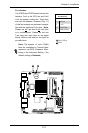
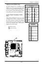
SATA DOM Power
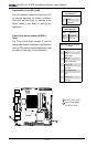
I2C Connector
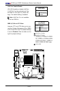
A
Chassis Intrusion
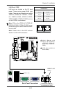
A Chassis Intrusion header is located
at JL1 on the motherboard. Attach the
appropriate cable from the chassis to
inform you of a chassis intrusion when
the chassis is opened.
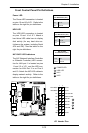
Chassis Intrusion
PinDenitions(JL1)
Pin# Denition
1 Intrusion Input
2 Ground
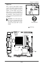
B
A
SATA DOM Power
The SATA DOM Power on JWF1 is used
to supply power to SATA Disk-on-Module
(DOM) solid-state storage devices.
B
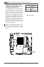
Power SMB I
2
C Connector
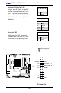
Power System Management Bus
(I
2
C) Connector monitors the status
of the power supply, fan and system
temperature. See the table on the right
for pin denitions.
PWR Supply I
2
C
PinDenitions
Pin# Denition
1 Clock
2 Data
3 PWR Fail
4 Ground
5 +3.3V
C
C