D14129.02—NOVEMBER 2008
57
Codec C90
Administrator Guide
Contents Introduction Getting started About the menus About the settings Settings Library Cameras Appendices Contact us
Appendices
TANDBERG Precision HD camera
The TANDBERG Precision HD camera does not automatically
adjust movement speed depending on zoom level. See the table for
suggested speed values when moving the Precision HD camera.
Movement speed for Precision HD camera
Zoom Level Pan Speed Tilt Speed
0..922
6 7
923..1845
3 5
1846..2768
1 3
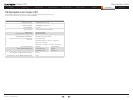
TANDBERG Precision HD camera
Description Ranges
Pan 0..816
Tilt 0..89
Zoom 0..2768
Focus 4096..4246
VISCA
Daisy
chain
Power in
12 V DC
HDMI
video
out
Camera
control &
Power
Kensington
lock
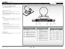
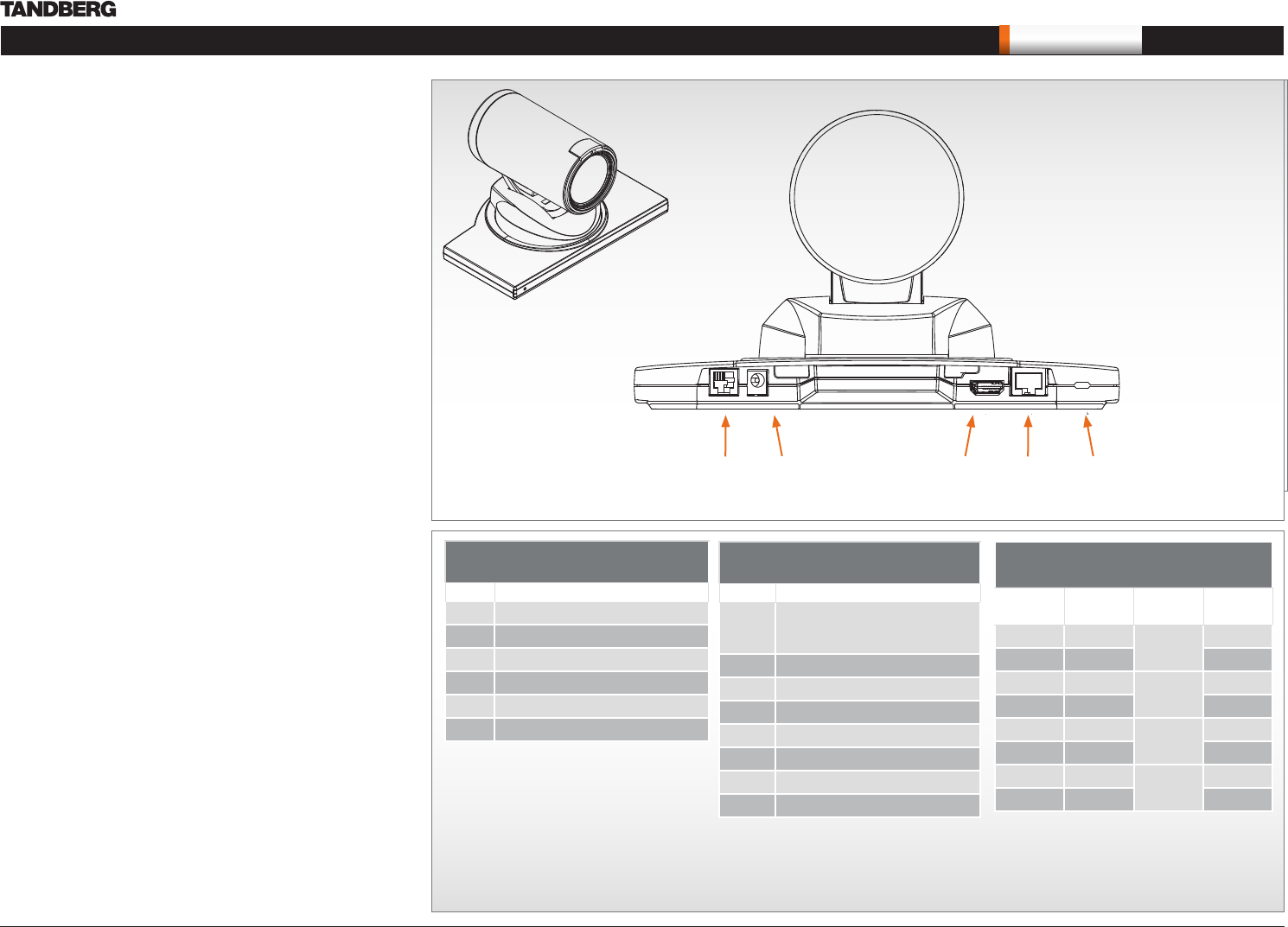
The PrecisionHD camera
This page describes the TANDBERG PrecisionHD camera, which was
the first TANDBERG HD camera.
Connecting the camera
Video out. For video out signals, connect from the HDMI on the
camera to a HDMI video input on the codec.
Power and camera control. For power in and camera control,
connect from the camera control & power on the camera to the
Camera port on the codec.
HDMI
HDMI is the main source for video out when connected to a Codec •
C90. Maximum resolution is 1280x720p30
This output does not support HDCP (High Bandwidth Digital •
Content Protection).
Cascaded cameras
The sockets named Extra Camera and Power In are used when
connecting cameras in daisy chain.
The first camera in the chain is powered up by the camera control •
cable. The next cameras must use the 12V DC Power in.
The daisy chained cameras are connected by using an extra •
camera cable (maximum length ## m) between the Extra Camera
sockets.
Kensington lock
The Kensington lock may be used to prevent the camera to be moved
from its place or to prevent theft.
EXTRA
CAMERA
12V DC IN
POWER
HD
VIDEO OUT
HDMI
HD
VIDEO OUT
CODEC
KENSINGTON
LOCK
Pin-out—VISCA Daisy chain
RJ 6 pins modular jack
Pin Signal name
6 GND
5 GND
4 RXD (in)
3 TXD (out)
2 Presence (12V in daisy chain)
1 GND
Pin-out—TANDBERG camera cable
RJ45 (8 pin) to D-SUB
Signal
name
RJ45
pin
D-SUB
pin
+12V DC 1 Twisted
pair
4
GND 2 5
RX 3 Twisted
pair
2
TX 6 3
NC 4 Twisted
pair
1
NC 5 6
GND 7 Twisted
pair
5
+12V DC 8 4
Pin-out—VISCA camera control
RJ 8 pins shielded modular jack
Pin Signal name
8 +12V (presence 2.8mA current
source when connected in daisy
chain)
7 GND
6 TXD (out)
5 NC (no connect)
4 NC (no connect)
3 RXD (in)
2 GND
1 +12V


