


116467.05
Page 2 of 6
4
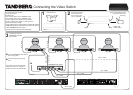
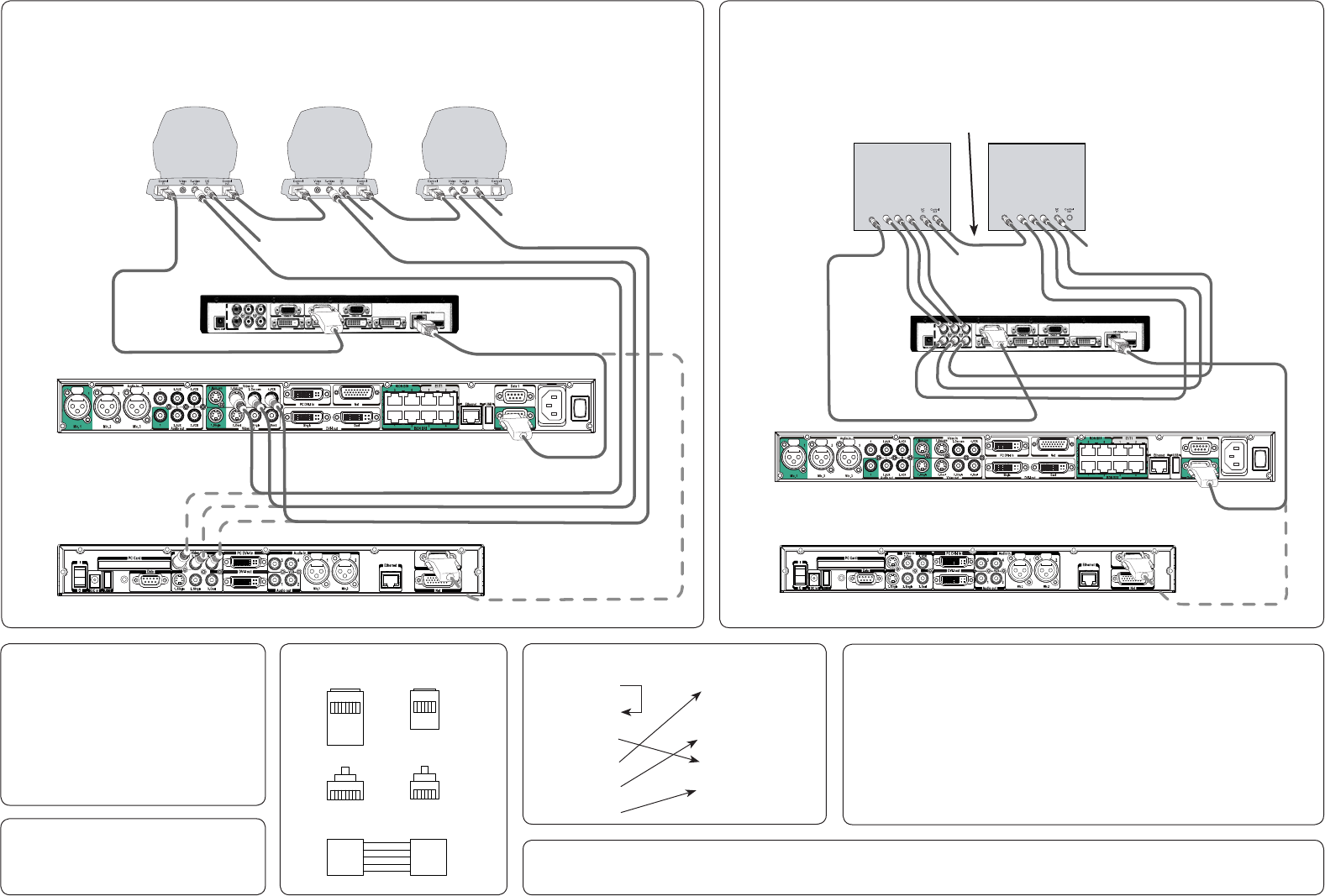
This diagram shows the additional connections needed to expand from using up to four TANDBERG
Precision HD cameras (see overleaf) to also include up to three TANDBERG WAVE II cameras
(i.e. up to seven cameras in total). Connect Video Switch power supply as shown overleaf.
5
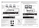
This diagram shows the connections needed to use a maximum of two analog sources
equipped with component video outputs. Connection diagram uses Sony EVI-
HD1 cameras as example. System supports 1280X720p50, 1280X720p59,94, and
1280X720p60 only. For full VISCA control Sony EV1-HDI cameras or true compatibles
must be used. Other units may or may not be partly or fully controllable. Connect Video
Switch power supply as shown overleaf.
You may combine TANDBERG HD Precision cameras with analog
sources equipped with component video outputs. Just add them to the
chain of cameras in the diagram shown overleaf, but make sure the
added sources appear after the TANDBERG HD Precision cameras in
the chain (i.e. after camera 4 in the diagram overleaf).
Consequently, up to four TANDBERG HD Precision cameras may be
combined with up to two analog component video sources and up to
three TANDBERG WAVE II cameras, bringing the maximum number of
video sources (which in many cases will be all cameras) up to nine!
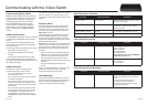
To upgrade the software of the Precision HD
camera, connect the camera directly to the
main camera socket of the Codec (the socket
that otherwise is used when connecting the
Video Switch to the Codec).
Power the units and the upgrade will start
automatically. The status will be shown on the
video system’s monitor.
RJ45
Top
RJ45
Front
1
8
1
8
RJ11
Top
RJ11
Front
18
16
RJ45 RJ11
1
2
3
6
7
2
1
3
4
5
TANDBERG RJ 45 – RJ 11
SONY Part Numbers: DB9–Mini DIN cable
SONY part number RC893
Mini DIN–Mini DIN chain cable
SONY part number RC815
SONY Mini DIN Precision HD RJ 11
1 DTR 1 GND
2 DSR 2 Not Used
3 TXD 3 TXD
4 GND 4 RXD
5 RXD 5 GND
6 GND 6 GND
Note!
Start by connecting
the Precision HD
cameras as shown
overleaf. The
connection shown
here comes in
addition to the one
overleaf!
Audio out
Data
Net
PC Card
1. Single 2. Single
Vide o out
Video in
3. Dual
2. Aux
3. Doc 4. VCR
VCR
Ethernet
PC DVI-I in
DVI-I out
1
2
4
Audio in
1
Mic.1
2
Mic.2
3
USBUSB
DC in
I
O
Camera
Connect WAVE
camera power
supply here.
RJ 11 – RJ45 RJ 11 – RJ45
S-video – S-video
RCA – RCA
RCA – RCA
RJ 45 – DB 9
RJ 45 – DB 9
Camera 1 Camera 2 Camera 3
TANDBERG 6000 MXP Codec
TANDBERG 3000 MXP Codec
Control
in
Control
in
Audio out
Data
Net
PC Card
1. Single 2. Single
Vid eo ou t
Video in
3. Dual
2. Aux
3. Doc 4. VCR
VCR
Ethernet
PC DVI-I in
DVI-I out
1
2
4
Audio in
1
Mic.1
2
Mic.2
3
USBUSB
DC in
I
O
Camera
Connect camera power
supply here.
Camera 1 Camera 2
DB 9– Mini DIN
RCA – RCA
RCA – RCA
Mini DIN – Mini DIN
TANDBERG 6000 MXP Codec
TANDBERG 3000 MXP Codec
RJ 45 – DB 9
RJ45–DB9 pinout is described in the
TANDBERG MXP Reference User Guide
for System Integrators, which came with
your TANDBERG Codec.
Secondary chain
The Codec must be equipped with
software version F6.1 or higher to
support the use of the Video Switch.
The Codec must be equipped with
software version F6.1 or higher to
support the use of the Video Switch.