17
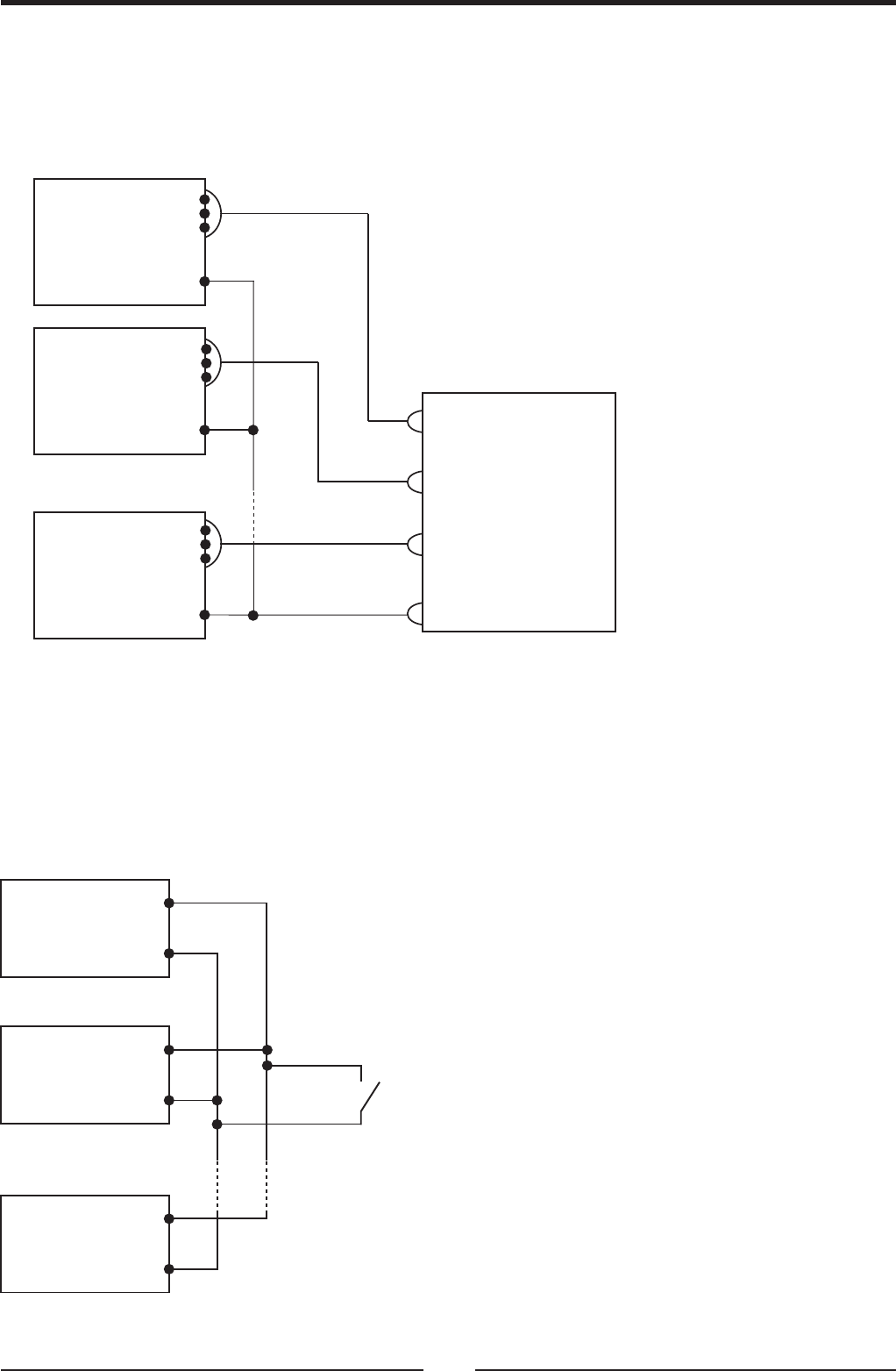
Fig 6-3: Signal Return connection at parallel operation
Fig 6-4: Remote On/Off control at parallel operation
6.1.3 Signal Return bus at parallel operation
The Signal Return of each paralleled unit can be connected together to form a common Signal Return bus.
By this way, the control and monitoring signals of the paralleled units can be connected to the same control and
monitoring circuitry.
The Signal Return bus can be connected to the -V or -S or +V or -S or float. Fig 6-3 shows typical connection of
the Signal Return at parallel operation.
6.1.4 Remote On/Off control at parallel operation
The paralleled units can be turned On or Off via a single On/Off control. Refer to Fig 6-4 for typical application. The
Signal Return function of all the paralleled units should be connected together to create a common Signal Return
bus. The Signal Return bus may be connected to the -V or the +V potential or floated. In any case do not connect
the Signal Return bus to different potentials.
ON OFF
FPS1000 #1
SIG.
RETURN
ON/OFF
FPS1000 #2
SIG.
RETURN
ON/OFF
FPS1000 #N
SIG.
RETURN
ON/OFF
7
10
7
10
7
10
FPS1000 Instruction Manual
FPS1000 #1
SIG.
RETURN
AC_FAIL
DC_OK
9, 11, 12
10
10
10
FPS1000 #1 SIGNALS
FPS1000 #2 SIGNALS
FPS1000 #N SIGNALS
SIGNALS RETURN
OVER-TEMP
ALARM
FPS1000 #2
SIG.
RETURN
AC_FAIL
DC_OK
OVER-TEMP
ALARM
FPS1000 #N
SIG.
RETURN
AC_FAIL
DC_OK
OVER-TEMP
ALARM
9, 11, 12
9, 11, 12
CONTROL AND
MONITORING CIRCUITS


