


EISA Fast SCSI Caching Adapter
12
Chapter 1
HARDWARE SETUP
Before plugging the DC-820B into your system, make sure all jumpers on the
card are correctly set according to instructions outlined in section 1.1. Also
take care that the SCSI ID number (0-6) of each SCSI device is set properly
for the host adapter (ID 7) (if necessary, check the user manuals for the
respective devices). Correct cable connections and termination are also nec-
essary for the adapters to function flawlessly. Refer to the following section,
Board Layout and Jumper Setting, for the exact location and setting of
jumpers.
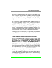
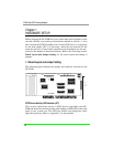
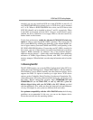
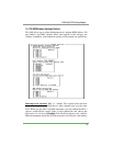
1.1 Board Layout and Jumper Setting
The following figure illustrates the jumper and connector locations for the
DC-820B.
TO SPKER
CPU
FIRMWARE.2
FIRMWARE.1
BIOS
DC-820B
JP1
TO LED
JP2
1
FDC
Active
Terminator
Active
Terminator
1
TO SCSI DISK DRIVE
CN2
TO FLOPPY DISK DRIVE
1
11
CN3
82355
BMIC
82355
BMIC
DC-820B
ASIC
CN1
External
SCSI
Connector
JP3
Floppy Enable
SCSI-II
Chip
Fast
1
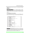
SCSI Device Activity LED Indicator (JP1)
JP1 is used to indicate the activity of SCSI devices controlled by the DC-
820B and should be connected to the cable leading to HDD LED on the front
panel of your system case. This LED also flashes some diagnostics codes
right after power-up. Refer to Appendix C for more details.