Telect, Inc. • USA +1.509.926.6000 • Mexico +52.33.3836.3700
Poland +48.713.239.100 • UK +44.1489.889500 • www.telect.com
Copyright © 2006 Telect, Inc., All Rights Reserved • 130358-2 A0
Page 6
13. Make sure power is off [open breaker, dummy fuse, or vacant fuse holder at power distribution unit (PDU)] before connecting
this panel’s cables to PDU.
14. Make sure that only dummy GMT fuses are install in this panel or that the GMT fuse holders are vacant.
15. Enable fuse or breaker at PDU (25A max. for Model 06004-01; 35A max. for Model 06004-11 which contains a fail-safe circuit)
to turn on Feed A to Side A of panel.
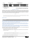
16. Check voltage and polarity at input connectors of panel. Also, check that —
•The A LED on front of panel turns on (green).
•The B LED must remain red.
If the A LED doesn’t turn green, recheck polarity at input connectors. (Reversing input
connections will not harm the panel.) If the input power leads were reversed, the fuse fail
relay will fail to energize causing the normally open contacts to remain closed and nor-
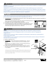
mally closed contacts to remain open. If necessary, check across the FAIL RELAY alarm pins located on the rear of the panel,
and shown above.
17. On the rear of the panel, with A LED lit (normal operation) — but with B LED off (failure operation) — test the
Side-A FAIL RELAY pins:
• Expect continuity (0Ω) between Terminals C and NC.
• Expect an open circuit (∞Ω) between Terminals C and NO.
Conversely, when testing the Side-B pins
—
•Expect an open circuit (∞Ω) between Terminals C and NC.
•Expect continuity (0Ω) between Terminals C and NO.
18. Repeat Steps 15 to 17 for Feed B and observe that the B LED turns green. Across all FAIL RELAY alarm pins —
• Expect continuity (0Ω) between Terminals C and NC.
• Expect an open circuit (∞Ω) between Terminals C and NO.
19. For output wiring
, strip off ¼ in. (~7 mm) of insulation.
Like the input terminals, the output terminals are screw-tight, wire-clamping. The output terminals will accommodate 14 AWG to
6 AWG conductors. Like the output terminals, stranded wires for outputs should be tinned.
Remember: Output conductors must be rated at or above the amperage rating of the GMT fuse. For example, use no smaller
than #16 AWG output wiring for 10A output fuses. Do not exceed 8A continuous load for a 10A fuse.
ALERT
!
ALERT! GMT fuses have a small inherent electrical resistance resulting in a small inherent power loss. For
this reason, the GMT fuse manufacturer recommends that the load for GMT fuses up to and including 7.5A not
exceed 80% of the fuse rating and that the load for 10A GMT fuses not exceed 70% of the fuse rating. (For ex-
ample, 10A fuse x .70 = 7A max. load). Total load for all GMT outputs on each side must not exceed 20A for a
panel without a fail-safe circuit, or 15A for a panel with a fail-safe circuit.
20. Telect recommends that you lightly coat anti-oxidant on bare wires before connecting to out-
put terminals. (NEC specifies only one conductor and load for each output terminal.) Tighten
screws to 4.5 in.-lb (0.51 N•m).
21. Connect other end of output wires to load.
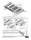
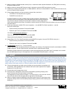
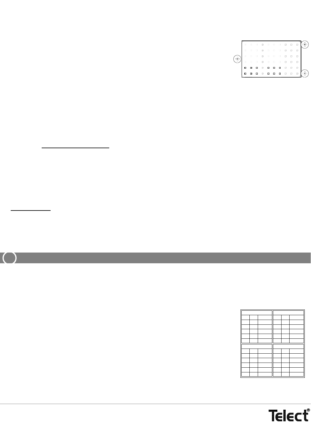
22. Record circuits on designation card provided, as specified by operating company proce-
dures.(The front side of the card is shown on the right.)
The designation card has entries for Outputs 1-10 on the front and 11-20 on the rear. Use the
left half of each side for Side A outputs and the right half for Side B outputs.
23. Make sure inputs at loads are disabled by removing all power cards or all input fuses at load
equipment. (Always follow recommended operating company guidelines when disabling load
equipment.)
FAIL
RELAY
NO
C
NC
A
B
NO
C
NC
INPUT FUSE
FUSE
1
2
3
4
5
AMP
CIRCUIT
INPUT FUSE
FUSE
1
2
3
4
5
AMP
CIRCUIT
INPUT FUSE
FUSE
6
7
8
9
10
AMP
CIRCUIT
INPUT FUSE
FUSE
AMP
CIRCUIT
6
7
8
9
10


