Telect, Inc. • USA +1.509.926.6000 • Mexico +52.33.3836.3700
Poland +48.713.239.100 • UK +44.1489.889500 • www.telect.com
Copyright © 2006 Telect, Inc., All Rights Reserved • 130358-2 A0
Page 7
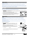
WARNING
!
WARNING! Use only UL-listed or UL-recognized component secondary protection devices.
24. Insert the proper sizes of GMT fuses in designated fuse holders using the designation card to identify circuits. Check voltage
and polarity at input of loads.
25. After all designated GMT fuses have been installed
, check that the A and B LEDs are still green. If an output fuse blows, the
corresponding A or B LED will turn red; if an input fuse blows, the corresponding A or B LED will be orange or amber.
Again, test FAIL RELAY alarm pins on rear of panel. As before —
• Expect continuity (0Ω) between Terminals C and NC.
• Expect an open circuit (∞Ω) between Terminals C and NO.
26. If available, replace one of the output fuses with a blown fuse and check that the A or B LED changes to red. Check the FAIL
ALARM pins again:
• Expect an open circuit (∞Ω) between Terminals C and NC.
• Expect continuity (0Ω) between Terminals C and NO.
When finished, re-install the operable fuse.
27. Do the same with one of the input fuses. Notice that the A or B LED changes to amber. The FAIL RELAY alarm pins will indicate
a failure condition.
28. If desired
, wire-wrap remote external audio/visual alarm in-
dicator wires (solid copper wires, #22 to #18 AWG) to the
alarm terminals. See “Alarm Terminal Wiring,” in the next
subsection.
29. One by one, re-enable load equipment and verify proper op-
eration.
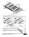
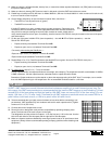
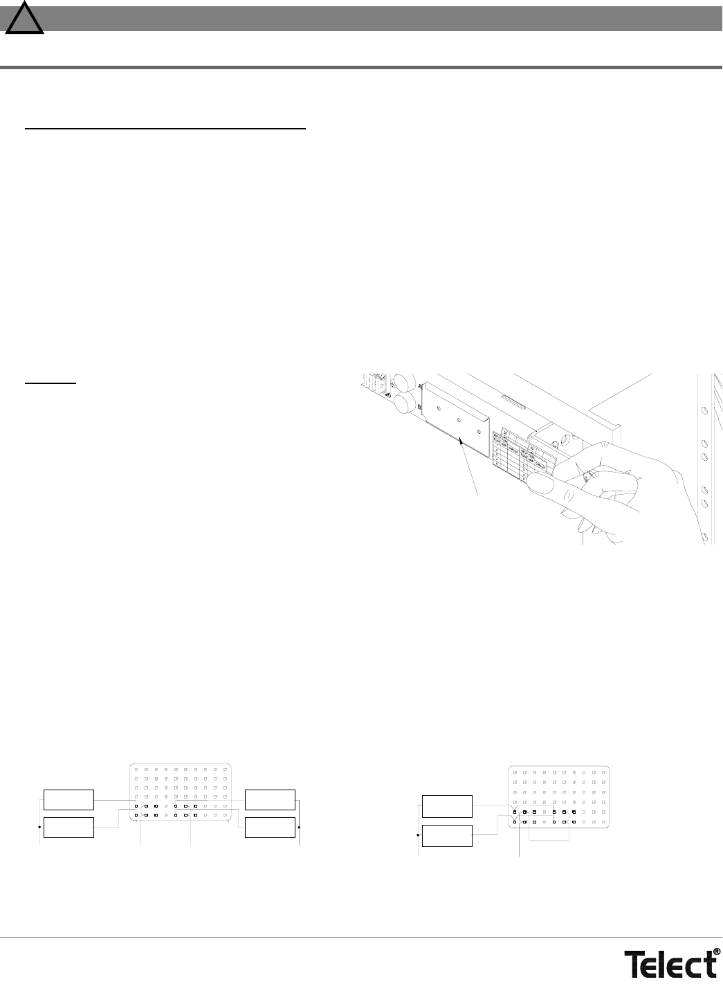
30. Fold designation card on the score line and slip into holder
on front of panel, as shown on the right.
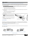
ALARM WIRING
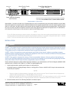
Model 06004-01 has a standard alarm relay (FAIL RELAY) for each feed — one for Side A and one for Side B. Models 06004-11
contains the standard alarm relay plus an auxiliary relay (AUX RELAY) that can be triggered externally. All relays have two sets of
Form C dry contacts for wiring to audible and visual alarm indicators.
Audible and/or visual failure indicators can be wired to the alarm pins in several ways.
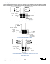
—— Standard Alarms
When an input or output fuse blows the relay is de-energized and the normally open contacts close and the normally closed contacts
open to indicate the failure.
Designation Card Holder
FAIL
RELAY
NO
CNC
A
B
NO
C
NC
NEG (or -GND)
+GND (or POS)
NEG (or -GND)
External
Alarm Device
External
Alarm Device
External
Alarm Device
External
Alarm Device
FAIL
RELAY
NO
C
NC
A
B
NO
C
NC
NEG (or -GND)
+GND (or POS)
External
Alarm Device
External
Alarm Device
a. Separate Alarms for Side A & Side B b. Combined Alarms for Side A & Side B
Standard Alarm Wiring


