Installation DNI-1B User Manual
2-4
Telect, Inc. 108891 Issue A Rev 2
INSTALLATION PROCEDURE
Mounting the DNI-1B
Step Action
1. Align the DNI-1B chassis mounting holes with the mounting holes
of the network bay/rack.
2. Install four mounting screws (two on each side) into the mounting
holes but do not completely tighten them.
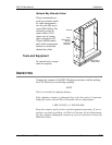
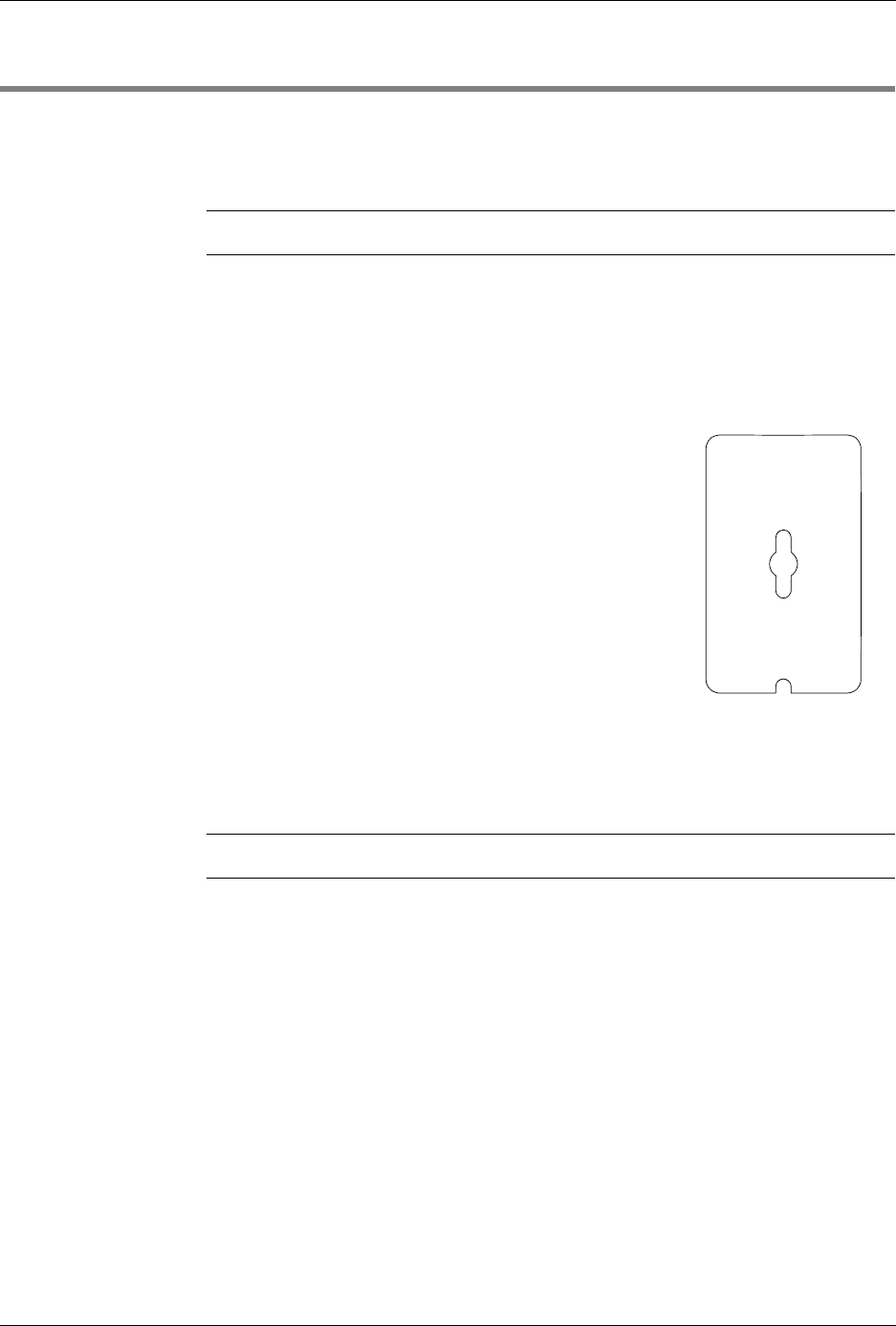
3. Attach the hinged label holders to the
front of the panel.
a. Slip the eyehole in the center of the
holder over the head of the top
mounting screw.
b. Slide the holder down on the shaft of
this screw so that the slot in the bot-
tom fits over the shaft of the bottom
screw.
c. Tighten both screws.
Cabling Procedure
Step Action
1. Route the DCS IN cables to one side of the network bay. Tie-wrap
the cables in place within the extender panel cable management
brackets.
2. Route the DCS OUT cables to the opposite side of the network bay;
tie-wrap them the same way.
3. Starting at the lowest DNI-1B panel in the bay/rack, lay the DCS IN
cables over the lower tie-down bar and connect them to the NE-1
IN termination points.
4. Secure the DCS IN cables to the tie-down bar.
5. Go to the next DNI1-B panel up and connect those DCS IN cables.
Continue the procedure, connecting all DCS IN cables.


