Issue A Rev 2 108891 Telect, Inc.
3-1
3 Electrical Operation
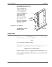
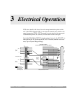
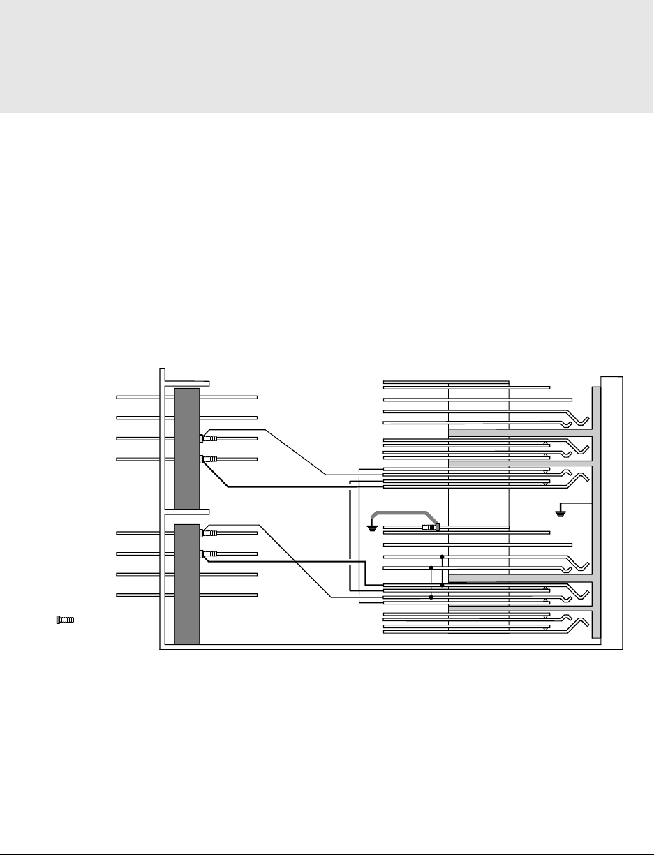
DCS wires attach to the lower four wire-wrap termination points on the
rear of the DNI-1B panel (NE-1); the network element wires attach to the
upper four points (NE-2). OUT (transmit) circuits attach to the upper pair
of termination points; IN (receive) circuits attach to the lower pair.
Inside the DNI-1B, the DCS IN circuits are hard-wired to the NE OUT cir-
cuits and the NE IN circuits to the DCS OUT circuits (internal cross-con-
nect, Tip-to-Tip and Ring-to-Ring):
NE-2
(NE)
NE-1
(DCS)
Out
Ground
(Green Wire)
Resistors
In
In
Out
T
R
T
R
T
R
T
R
Cutaway Side View of DNI1-B
Termination Points
Internal
Cross-
Connect
N
E
1
N
E
2
O
U
T
M
O
N
I
N
O
U
T
M
O
N
I
N
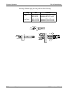
All internal con-
nectionsare wired,
not just chassis
ground and the
termination points.
DCS Out to NE In
Remaining Circuits Are Similarly Wired


