MIU Installation, Operation & Diagnostics Edition: January 25, 1999 Page 8
6. POWER CONNECTIONS
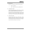
DC Power Jack, 2.0mm – This standard concentric jack is provided to attach an
external power source in the range of 7 – 16 VAC or 8 – 24 VDC. The 2.0mm
Jack connects through a full wave bridge so either polarity is acceptable from the
DC source. The slide switch adjacent to the LED must be to the right side
(Toward the 2.0mm Jack).
DB – 25, Pin 10 – A DC voltage may be applied at the 25 pin data connector. DC
only with the positive lead connected to pin 10, and the negative lead connected to
Signal Ground on pin 7. This should be a regulated 5 VDC source. The slide
switch adjacent to the LED must be to the left side (Away from the 2.0mm Jack).
Internal jumper JP1 must be on pins 1-2.


