


MIU202T Installation, Operation & Diagnostics Edition: April 4, 1998 Page 18
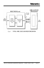
Test 3: Received Signal Level
Set Dip Switch 1 OFF (TxA = -10dBm) and Dip Switch 3 OFF
(RxA = -43dBm).
CD will be ON.
Run a test message at TxD and verify that the same message is
received at RxD with no data errors.
Test 4: Repeat Test 3 for various RTS/CTS delay times and with soft
carrier ON and OFF.
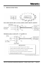
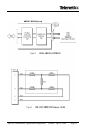
(b) LOCAL DIGITAL LOOPBACK – 4/Wire Network (Figure 4)
On the modem under test, connect TxD to RxD
Switch 1 = ON (TxA = 0dBm)
Switch 3 = ON (RxA = -33dBm)
Switch 4 = OFF (RTS/CTS = 35ms)
Switch 5 = ON (RTS/CTS = 35ms)
Switch 6 = ON (Constant Carrier mode).
Switch 7 = OFF (4-Wire)
Switch 8 = ON (Line Termination = 600 ohms)
Switch 9 = ON (Soft Carrier = ON)
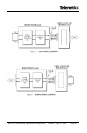
Transmit a test message from a remote modem and confirm that the same
message is received back at RxD on the remote modem with no data errors.