


MIU202T Installation, Operation & Diagnostics Edition: December 28, 2000 Page 16
13. DIAGNOSTICS
The following pages provide hardware techniques for diagnosing
communication problems and thereby isolating the problem at the local
modem, the remote modem or the interconnecting line.
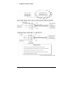
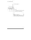
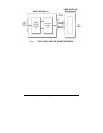
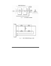
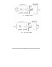
(a) LOCAL ANALOG LOOPBACK (Figure 2)
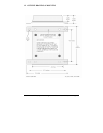
Requires a loop back cable with a built-in circuit for line loss to
simulate a typical leased line condition (See Figure 3).
Connect the loop back cable to the RJ11 connector on the modem
under test.
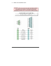
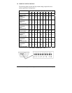
Set Dip Switches as follows…
Switch 7 = OFF 4-Wire
Switch 9 = ON Soft Carrier Turn Off Enabled
Switch 1 = ON Transmit (TxA) Signal Level = 0dBm
Switch 3 = ON Receive (RxA) Signal Level = –33dBm
Switch 6 = OFF Switched Carrier
Switch 4&5 = ON RTS/CTS Delay = 50ms
Test 1: RTS/CTS Analog Control
Set RTS “ON” and check that CD (Carrier Detect) turns
“ON”.
Turn RTS “OFF” and ensure that CD turns “OFF”
With RTS “ON”, run a test message at TxD and verify that
the same message is received at RxD with no data errors.
Test 2: Transmit Signal Power & Receive Levels
Set Dip Switch 1 OFF (TxA = -10dBm)
CD will be OFF.
Change Dip Switch 1 to ON (TxA = 0dBm)
CD should now be ON.
Test 3: Received Signal Level